|
| BT50 Rev B Pictorial Build Guide |
 |
|
 |
|
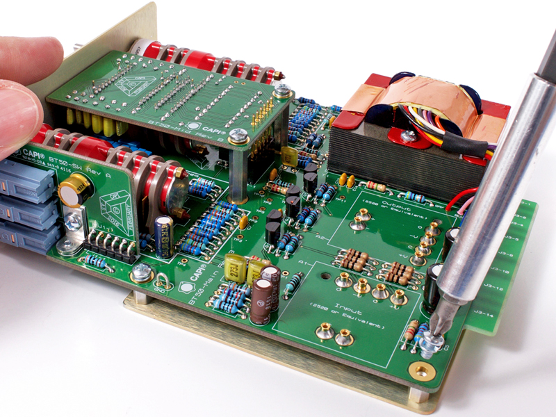
MAKE SURE the build guide you follow matches the Revision of the PCB you are building!
|
Click to enlarge
|
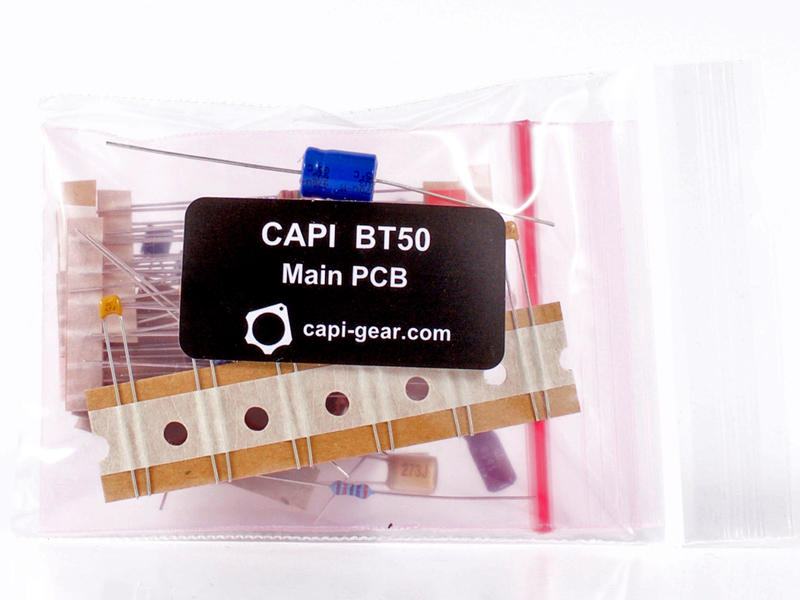
2.B.0 |
The follow capacitors can be found in the LC~MC~HC Capacitors bag.
|
 |
Click to enlarge
|
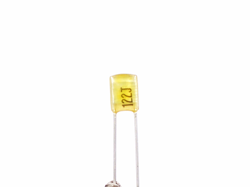
2.B.1 |
Nichicon .0012μF film capacitor, label is "122J"
|

Click to enlarge
|
2.B.2 |
Nichicon .0015μF film capacitor, label is "152J"
|
Click to enlarge
|
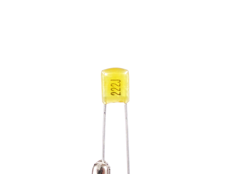
2.B.3 |
Nichicon .0022μF film capacitor, label is "222J"
|

Click to enlarge
|
2.B.4 |
Nichicon .0033μF film capacitor, label is "332J"
|

Click to enlarge
|
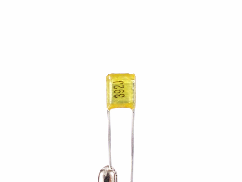
2.B.5 |
Nichicon .0039μF film capacitor, label is "392J"
|
Click to enlarge
|
2.B.6 |
Nichicon .0047μF film capacitor, label is "472J"
|

Click to enlarge
|
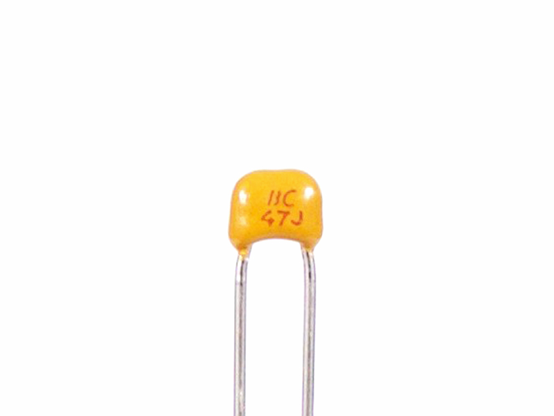
2.B.7 |
Nichicon .0056μF film capacitor, label is "562J"
|

Click to enlarge
|
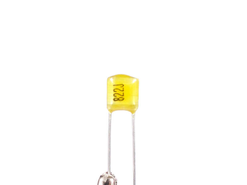
2.B.8 |
Nichicon .0082μF film capacitor, label is "822J"
|
Click to enlarge
|
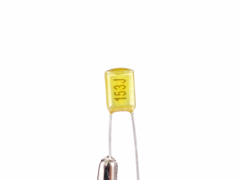
2.B.9 |
Nichicon .015μF film capacitor, label is "153J"
|
Click to enlarge
|
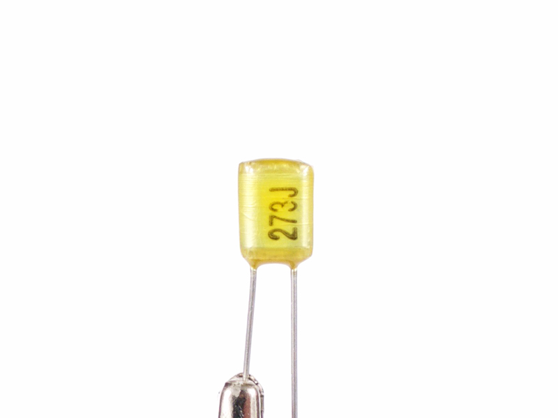
2.B.10 |
Nichicon .027μF film capacitor, label is "273J"
|
Click to enlarge
|
2.B.11 |
Nichicon .039μF film capacitor, label is "393J"
|
|

Click to enlarge
|
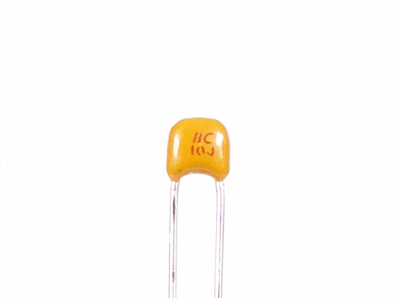
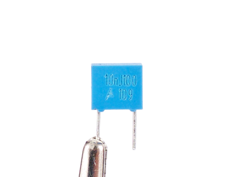
2.B.12 |
EPCOS / TDK .01μF film capacitor, label is "10nJ100"
|
Click to enlarge
|
2.B.13 |
EPCOS / TDK .015μF film capacitor, label is "15nJ100"
|
Click to enlarge
|
2.B.14 |
EPCOS / TDK .022μF film capacitor, label is "22nJ100"
|

Click to enlarge
|
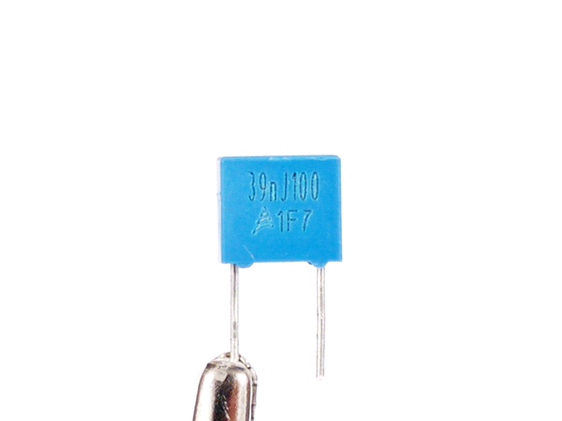
2.B.15 |
EPCOS / TDK .039μF film capacitor, label is "39nJ100"
|
Click to enlarge
|
2.B.16 |
EPCOS / TDK .068μF film capacitor, label is "68nJ100"
|

Click to enlarge
|
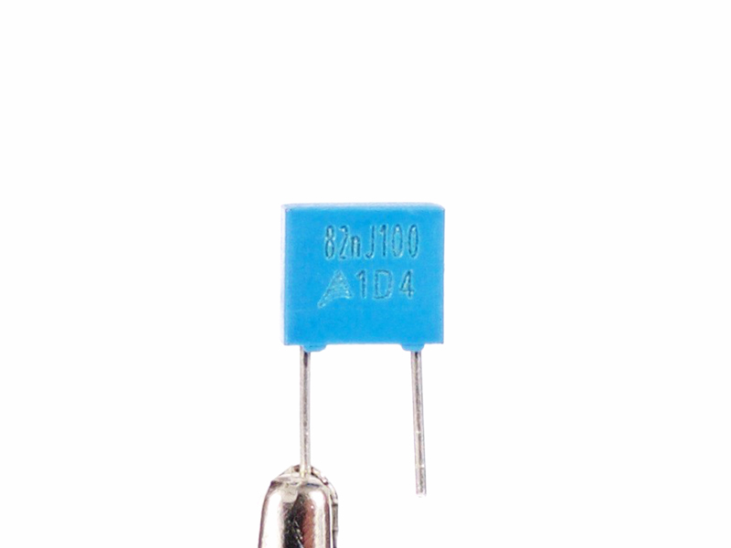
2.B.17 |
EPCOS / TDK .082μF film capacitor, label is "82nJ100"
|
Click to enlarge
|
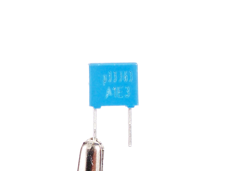
2.B.18 |
EPCOS / TDK .33μF film capacitor, label is "μ33J63"
|
Click to enlarge
|
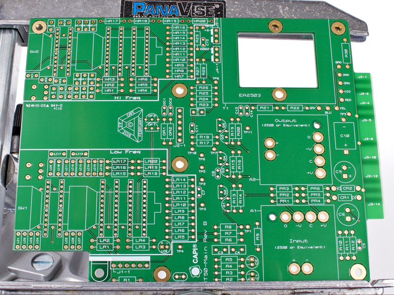
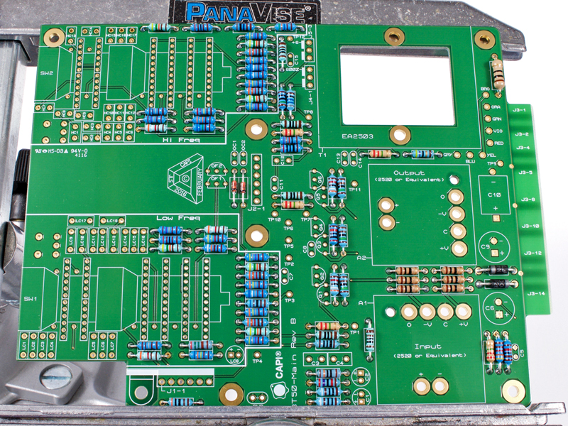
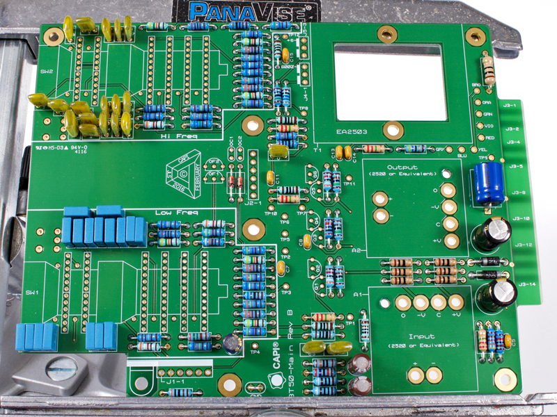
3.0 |
And we begin with a blank canvas.
|
|
Click to enlarge
|
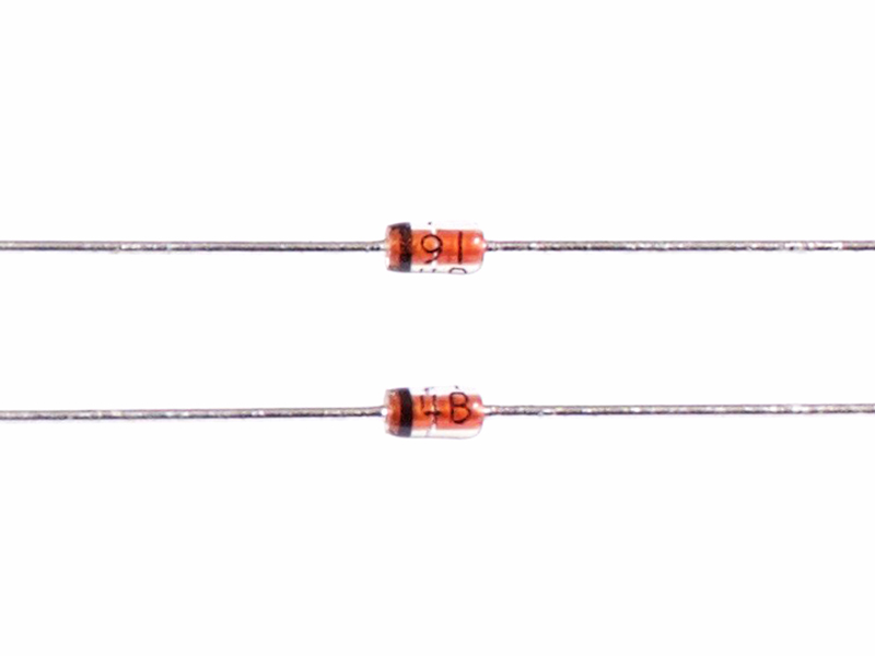
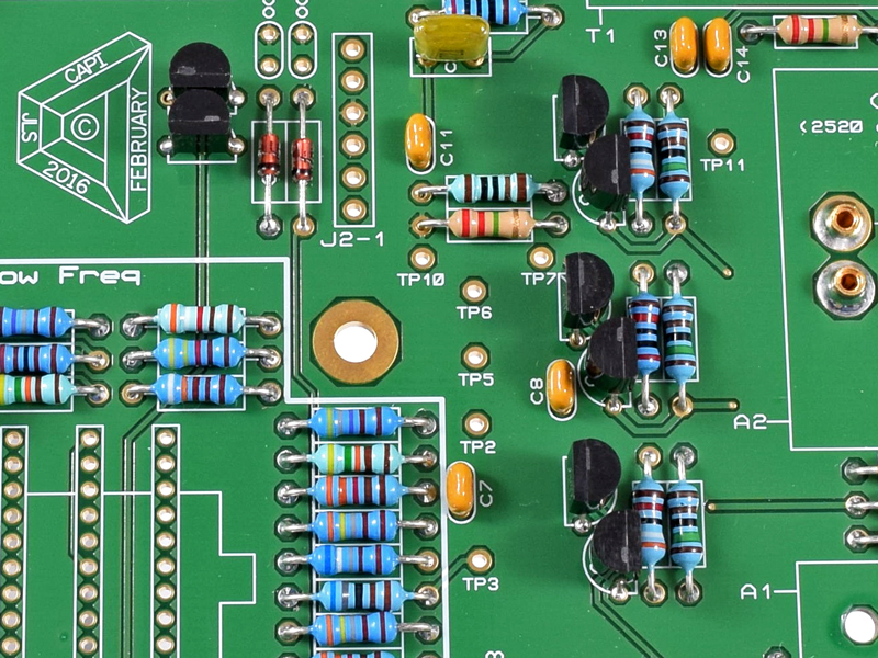
3.1 |
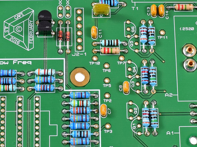
Identify and install the small package diodes. The silkscreen shows resistor labels but these are actually 1N914 diodes.
The black-banded cathode ends MUST go in the direction shown in the pic.
|
|
Click to enlarge
|
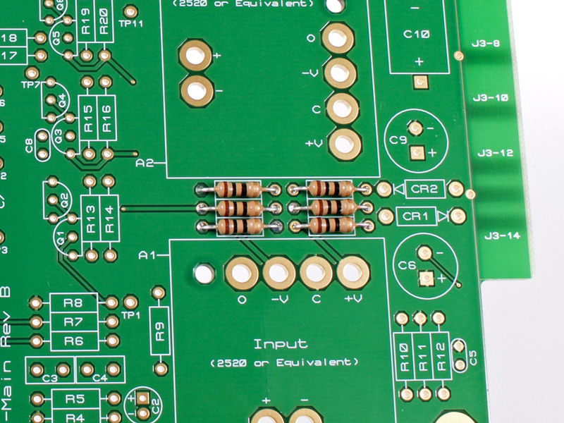
3.2 |
Locate and install all of the 10Ω power damping R's designated with PR.
|
|
Click to enlarge
|
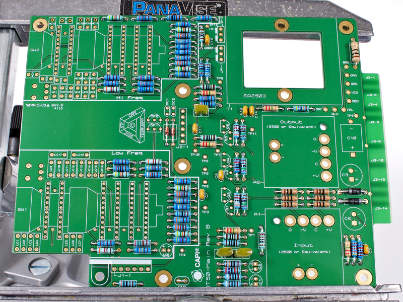
3.3 |
Identify and install all 1% .25W R's for the Main section of the PCB.
|
|
Click to enlarge
|
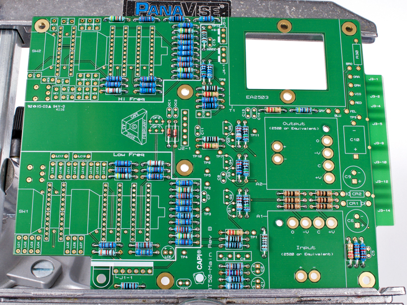
3.4 |
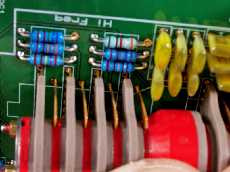
Identify and install all LR's for the Low Freq and HR's for the Hi Freq section of the PCB.
|
|
Click to enlarge
|
3.5 |
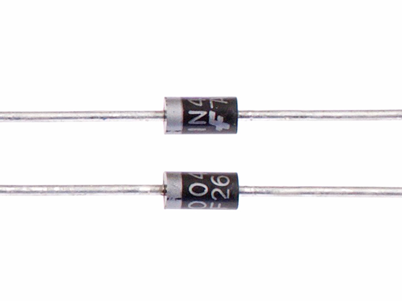
Install the large package diodes and the .5W resistor. Save a cutoff lead from a diode for the next step.
|
|

Click to enlarge
|
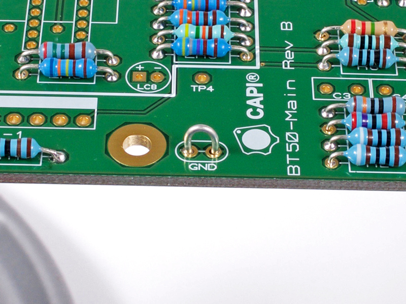
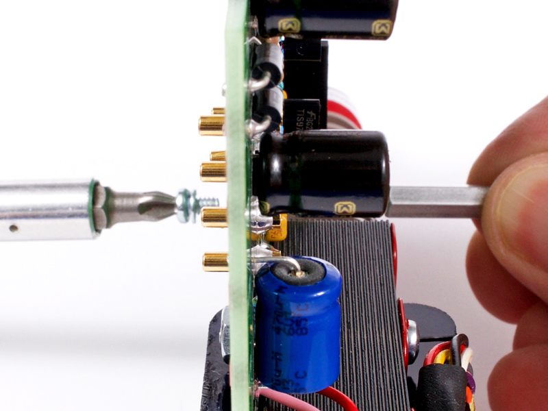
3.6 |
Bend the saved lead from step 5 over a small screwdriver tip and solder into the GND position. This is the preferred probe
hook location for testing.
|
|
Click to enlarge
|
3.7 |
Identify and install the small package ceramic capacitors.
**Please note: OC1 and OC2 are NOT used!!
|
|

Click to enlarge
|
3.8 |
Identify and install the main section film caps C3, C4 and C12.
|
|
Click to enlarge
|
3.9 |
Identify and install the Low Freq film caps LC1 thru LC4.
|
|
Click to enlarge
|
3.10 |
Identify and install the Low Freq film caps LC5 thru LC7.
|
|
Click to enlarge
|
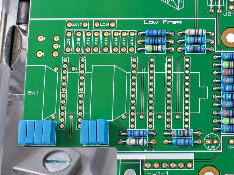
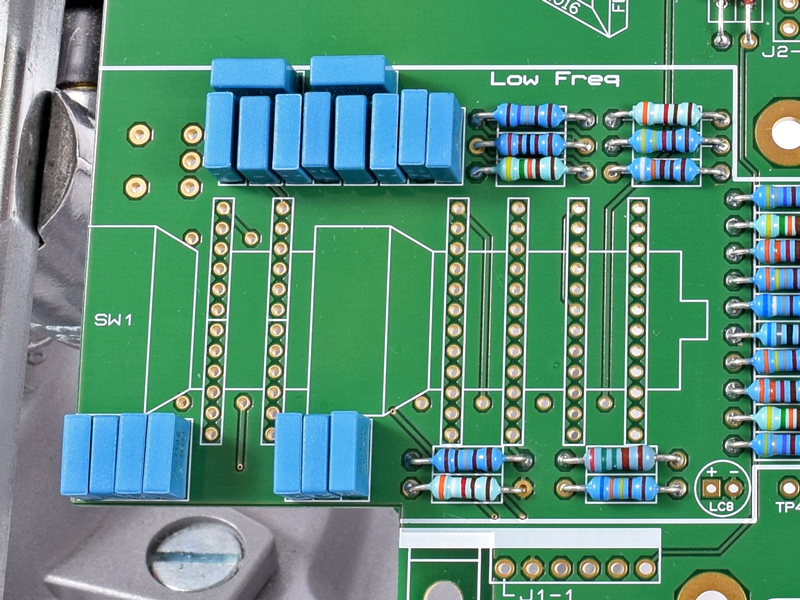
3.11 |
Identify and install the Low Freq film caps LC9 thru LC16.
|
|
Click to enlarge
|
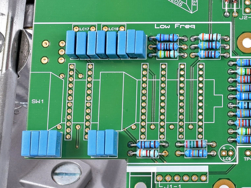
3.12 |
Identify and install the Low Freq film caps LC17 and LC18.
|
|
Click to enlarge
|
3.13 |
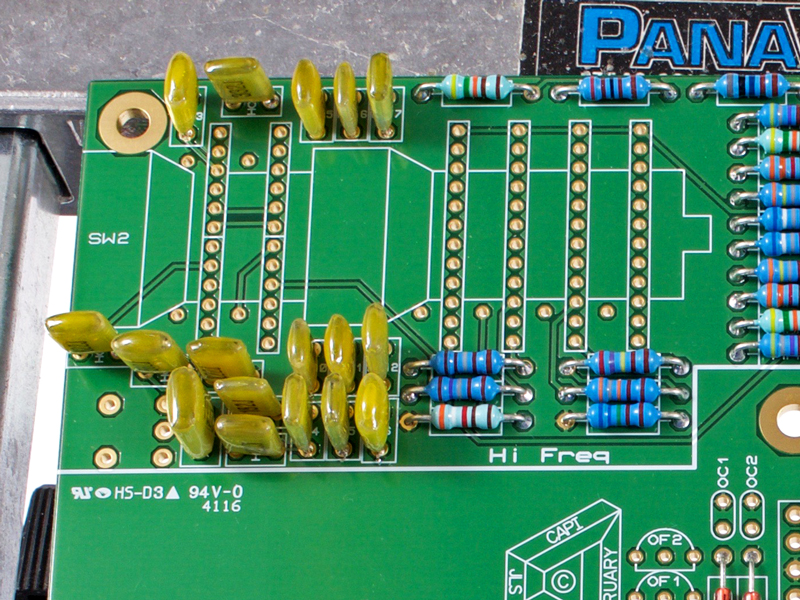
Identify and install the Hi Freq film caps HC1, HC4, HC5 and HC6.
|
|
Click to enlarge
|
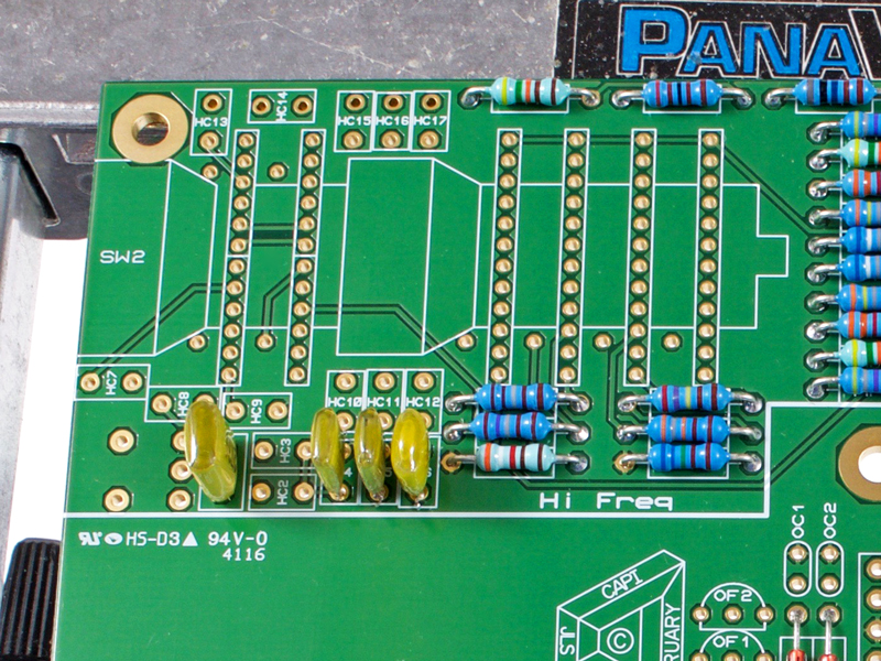
3.14 |
Identify and install the Hi Freq film caps HC7, HC10, HC11 and HC12.
|
|
Click to enlarge
|
3.15 |
Identify and install the Hi Freq film caps HC2, HC3, HC9 and HC14.
|
|
Click to enlarge
|
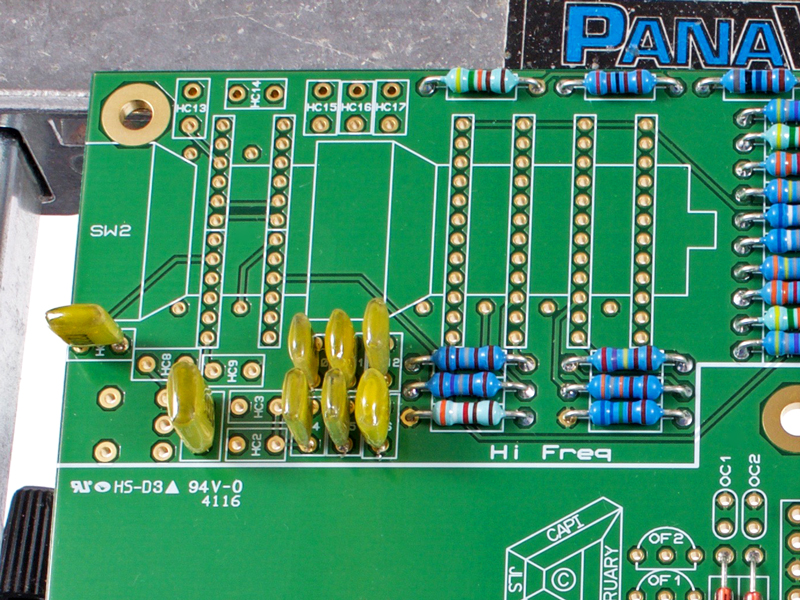
3.16 |
Identify and install the Hi Freq film caps HC8, HC13, HC15, HC16 and HC17.
|
|
Click to enlarge
|
3.17 |
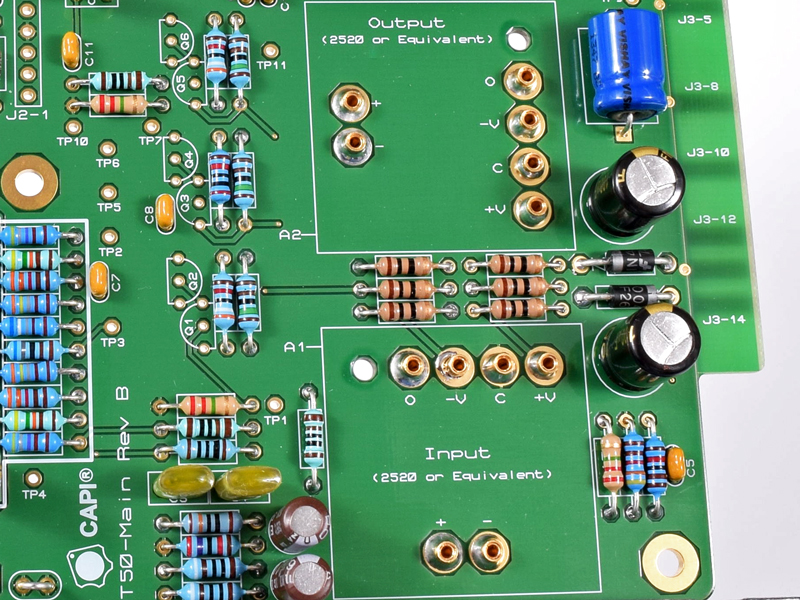
Identify and install all electrolytic caps LC8, C1, C2, C6, C9 and C10.
|
|
Click to enlarge
|
3.18 |
Install the opamp sockets for A1 and A2. These should be installed thru and only soldered at the bottom of the PCB. The
solder seen at the top has leaked thru during the process.
|
|
Click to enlarge
|
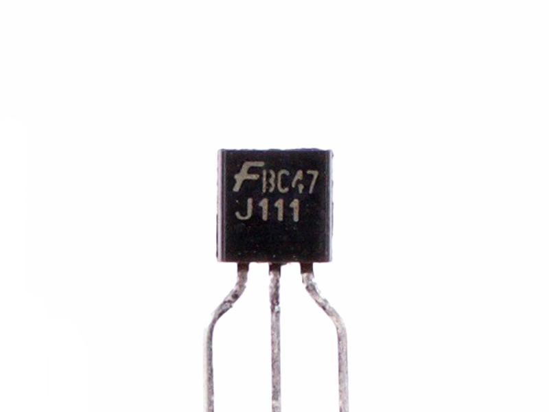
3.19 |
Identify and install the J111 FET's in OF1 and OF2. I alternate when soldering as to not overheat one of the parts.
|
|
Click to enlarge
|
3.20 |
Identify and install the TIS97 transistors in Q1, Q3 and Q5. Alternate soldering as recommended for the FET's.
|
|
Click to enlarge
|
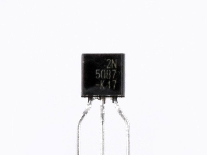
3.21 |
Identify and install the 2N5087 transistors in Q2, Q4 and Q6. Again, alternate soldering is recommended.
|
|
Click to enlarge
|
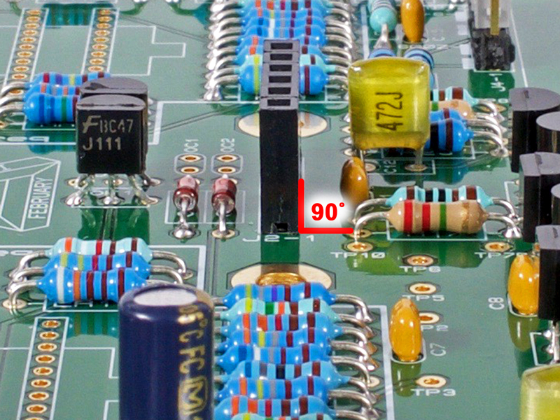
3.22a |
Solder only one pin of the 6-pin receptacle for J2.
|
Click to enlarge
|
3.22b |
Make sure the body of the receptacle is perpendicular to the PCB and solder all remaining pins.
|
|
Click to enlarge
|
3.23 |
Install the two 3-pin option headers and shunts for J4 and J5. Make sure they are perpendicular as mentioned above for J2.
The grey shunts are shown in the preferred startup positions.
|
|
Click to enlarge
|
3.24a |
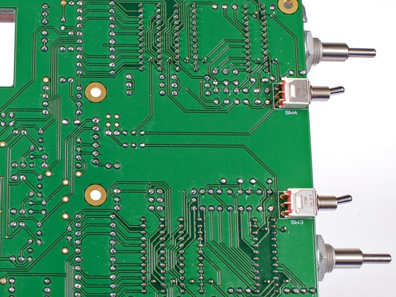
Install the two C&K mini toggle switches from the bottom of the PCB by soldering only one pin first.
|
Click to enlarge
|
3.24b |
Check to make sure they are seated parallel to the PCB.
|
Click to enlarge
|
3.24c |
Solder the remaining pins.
|
|
Click to enlarge
|
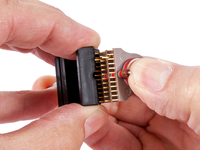
3.25a |
Carefully remove the black plastic protective covers from the 6-deck Grayhill switches.
|
Click to enlarge
|
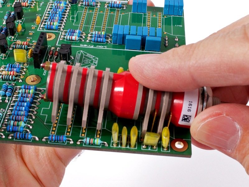
3.25b |
Start by slightly/partially inserting the pins at the shaft-end of the switch. Do not insert them all the way at this time.
|
Click to enlarge
|
3.25c |
Due to manufacturing tolerances, the pins of the rear decks may be slightly off from the PCB holes. I have already cheated
the hole pattern in the PCB beyond what the Grayhill spec sheet shows.
|
Click to enlarge
|
3.25d |
Gently apply rearward pressure from the shaft end while simultaneously applying slight downward pressure. Great patience
must be used. All of a sudden the switch will pop right into the holes.
|
Click to enlarge
|
3.25e |
Solder two pins at the front and two pins at the rear of the switch.
|
Click to enlarge
|
3.25f |
Double check the front and rear of the switch to make sure it is fully and evenly seated to the PCB. Adjust as required.
|

Click to enlarge
|
3.25g |
Solder the remaining switch pins. I recommend an alternating pattern to not overheat the innards.
|
|
Click to enlarge
|
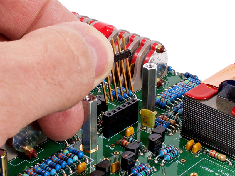
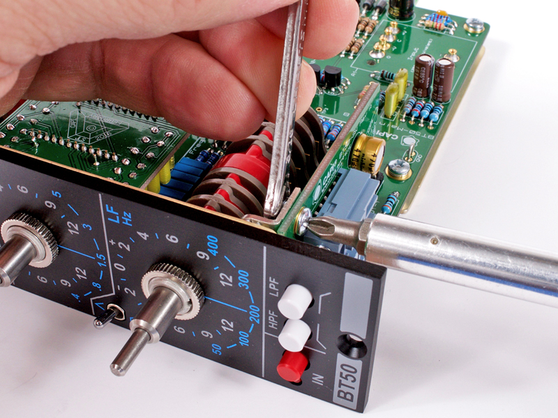
3.26 |
Install the other 6-deck Grayhill switch.
|
|
Click to enlarge
|
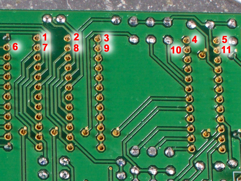
3.27 |
It is a necessity to inspect the switch pins with a magnifying glass. Be sure you have no solder
bridges!!
|
|
Click to enlarge
|
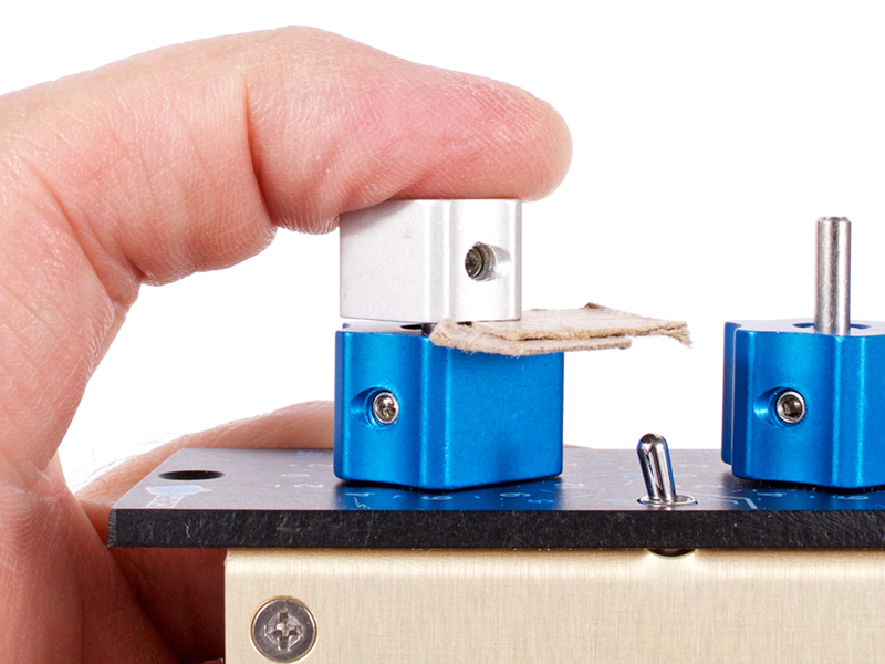
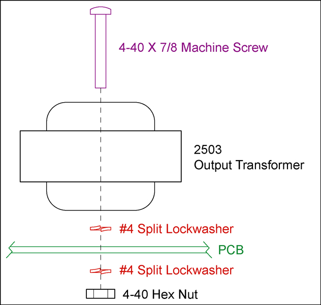
3.28 |
Install the 2503 style output transformer following the
2503 hardware guide.
I used the Litz version for these builds so I had to alter the lead's color code placement. For the Litz version, you
can use this pic as a reference or follow the chart on the bottom left of the
datasheet. For a standard EA2503, just match the lead's colors to their respective holes.
|
Click to enlarge
|
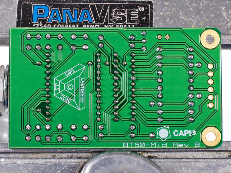
4.0 |
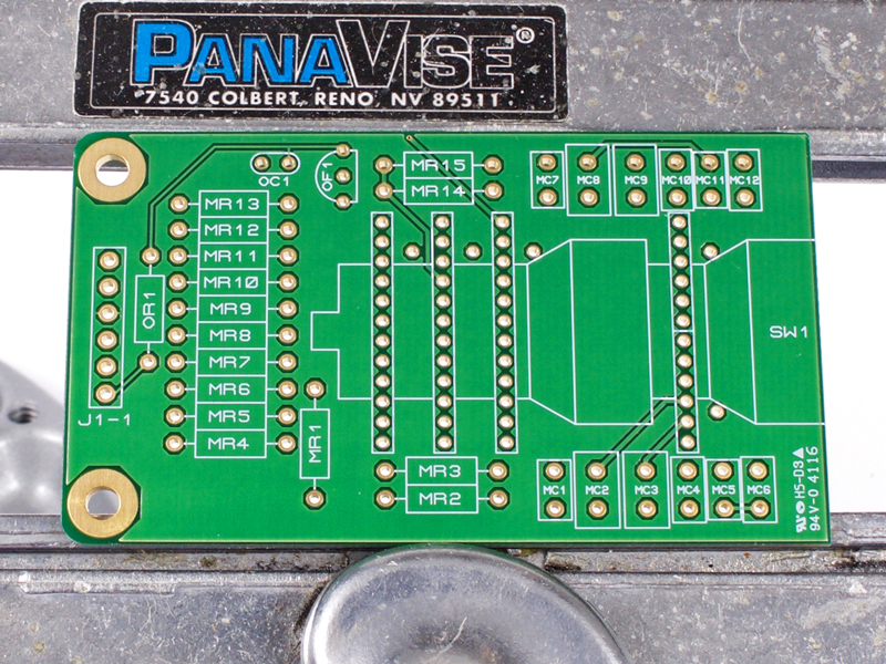
And we again begin with a blank canvas.
|
|
Click to enlarge
|
4.1 |
Identify and install the small package diode. The silkscreen shows a resistor label but its actually a 1N914 diode.
The black-banded cathode end MUST go in the direction shown in the pic.
|
|
Click to enlarge
|
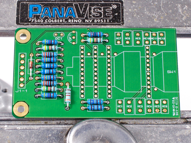
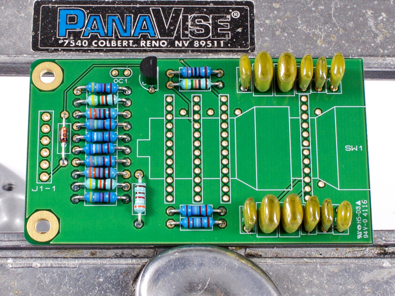
4.2 |
Identify and install all resistors for the PCB.
|
|
Click to enlarge
|
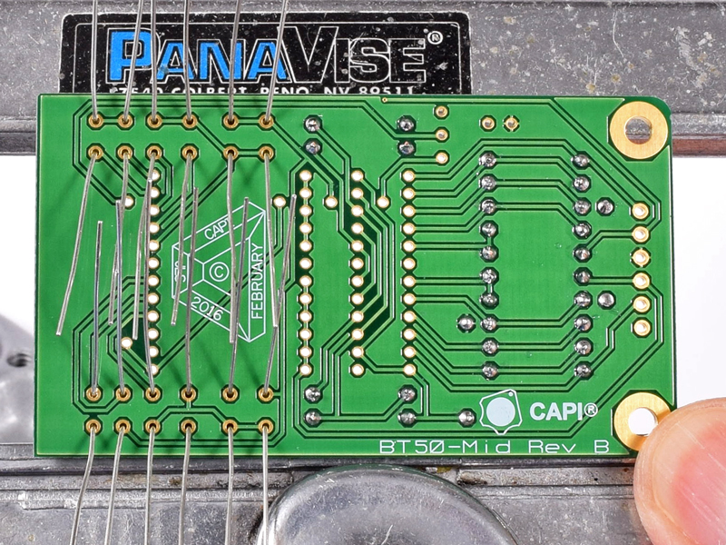
4.3a |
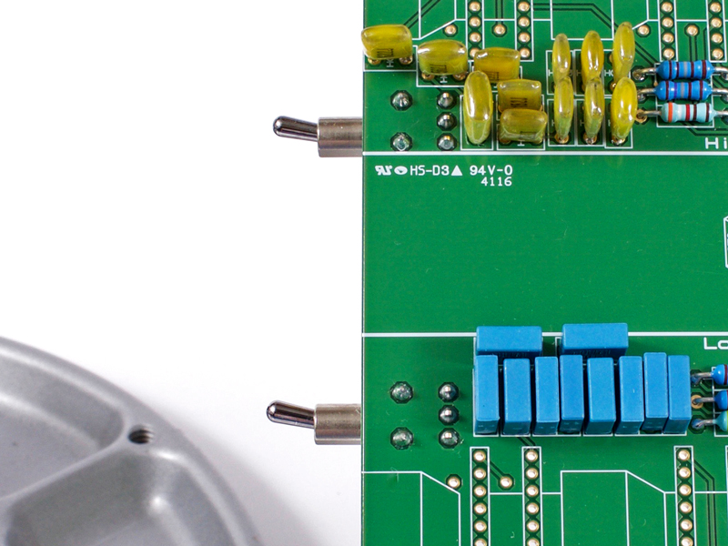
Identify and install all film caps. I do these all at once since the direction is the same and there's plenty of room
to bend all of the leads.
|
Click to enlarge
|
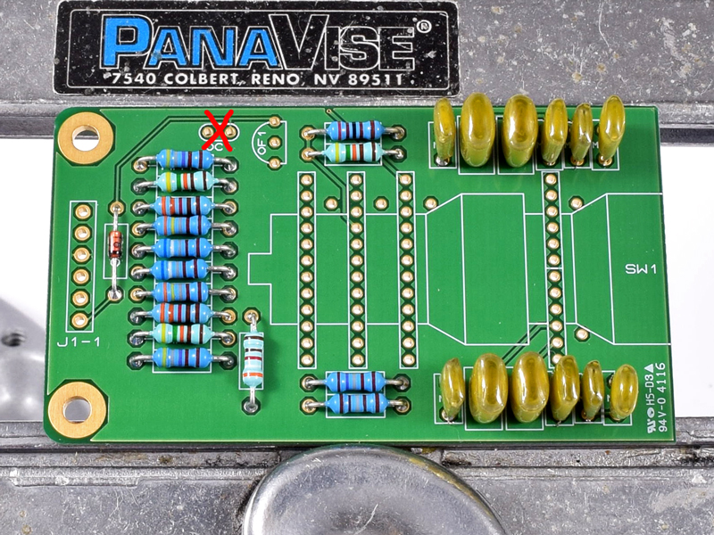
4.3b |
**Please note: OC1 is NOT used!!
|
|
Click to enlarge
|
4.4 |
Identify and install the J111 FET in OF1.
|
|
Click to enlarge
|
4.5a |
Install the 4-deck Grayhill switch using the same methods as described above. You will find this switch much easier due to
there being one less deck for each section.
|
Click to enlarge
|
4.5b |
Holding the switch during soldering can be tricky. Something like this makes the job easier.
|
Click to enlarge
|
4.5c |
Or something like this.
|
Click to enlarge
|
4.5d |
It is a necessity to inspect the switch pins with a magnifying glass. Be sure you have no solder
bridges!!
|
|

|
4.6 |
DO NOT install the 6-pin gold header at this time! That will happen during the final assembly steps.
|
Click to enlarge
|
5.0 |
And we again begin with the customary blank canvas.
|
|
Click to enlarge
|
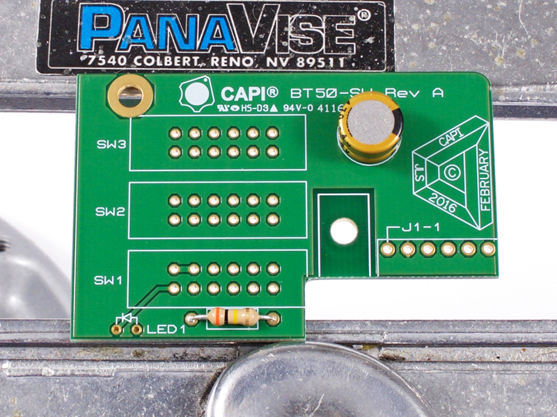
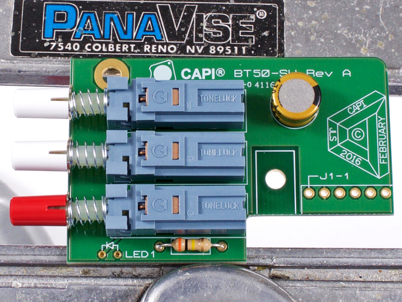
5.1 |
Install the lone resistor and capacitor.
|
|
Click to enlarge
|
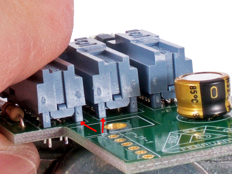
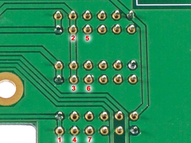
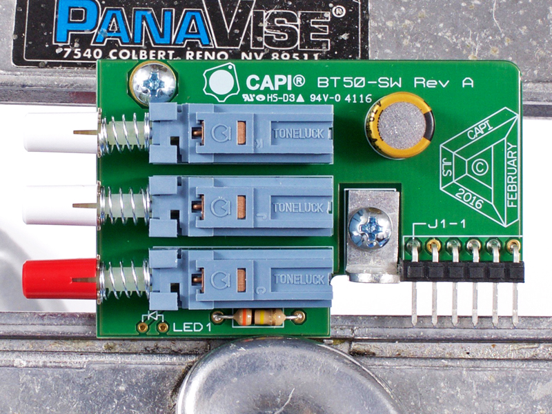
5.2a |
Start the install of the three 4PDT mini Toneluck pushbutton switches. Begin by soldering only 2 pins of each switch.
|

Click to enlarge
|
5.2b |
Before soldering all of the pins, check that the switches are fully seated at the rear. Adjust as required.
|

Click to enlarge
|
5.2c |
Also check that the fronts are fully seated. Adjust as required.
|
Click to enlarge
|
5.2d |
Solder the remaining switch pins using an alternating order to not overheat the switch innards.
|
Click to enlarge
|
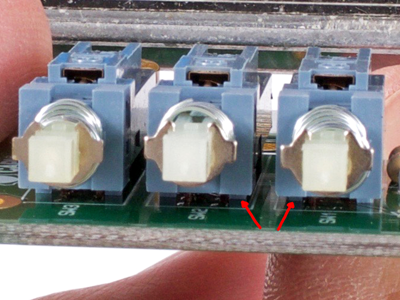
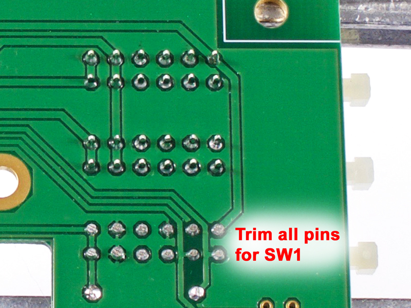
5.2e |
Trim all of the pins for SW1. This is mandatory not optional. During final assembly these pins will interfere with
caps on the main PCB if not trimmed.
|
|
Click to enlarge
|
5.3 |
Install the pushbutton switch caps.
|
|
Click to enlarge
|
5.4a |
Start the install of the 6-pin 90° header by soldering one of the pins. Check to make sure its seated properly.
|
Click to enlarge
|
5.4b |
Solder the remaining header pins at the bottom of the PCB.
|
|

Click to enlarge
|
5.5a |
Begin the install of the mounting hardware. Do not fully tighten at this time. Only finger tight.
|
Click to enlarge
|
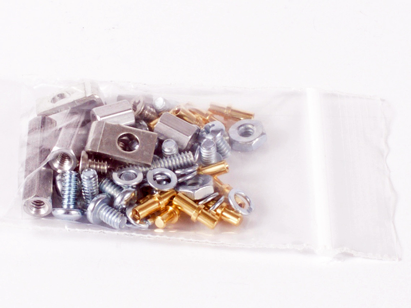
5.5b |
Secure the #616 Keystone brackets with 1/4" pan head screws, #4 lockwashers and 4/40 small pattern hex nuts.
|
|
Click to enlarge
|
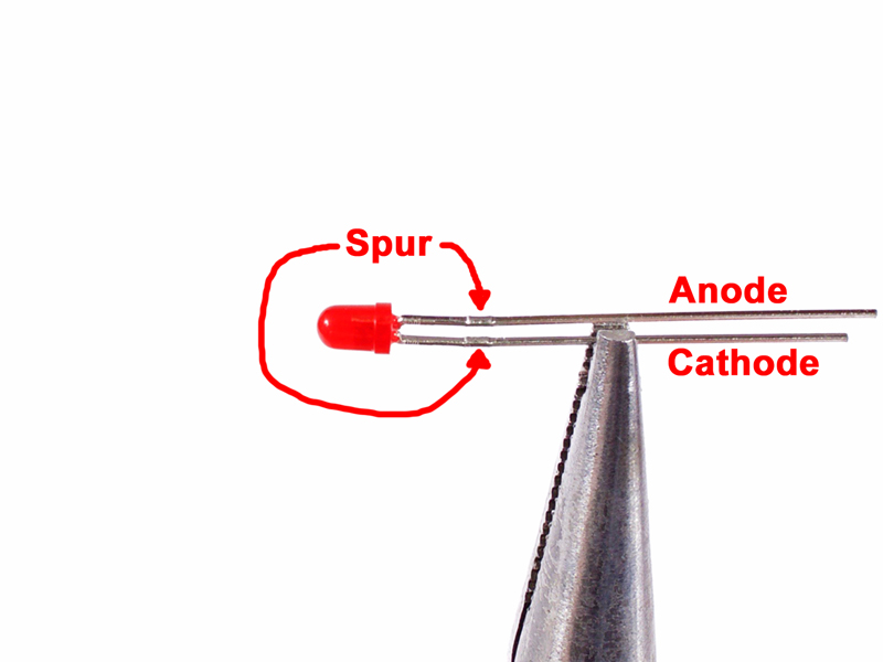
5.6a |
Locate the 3mm red LED and take note of the small spurs just below the body.
|
Click to enlarge
|
5.6b |
Using needle nose pliers, take hold of the shorter cathode lead, lining up with the bottom edge of the spur.
|
Click to enlarge
|
5.6c |
Bend the lead 90° downward.
|
Click to enlarge
|
5.6d |
Take hold of the longer anode lead approximately .1" lower than where the cathode is bent.
|
Click to enlarge
|
5.6e |
Bend anode lead downward so its parallel with the cathode lead.
|
|
|
5.7 |
DO NOT install the LED at this time! That will happen during the final assembly steps.
|

Click to enlarge
|
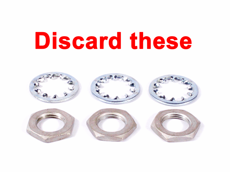
6.1 |
Remove the nuts and lockwashers from the three Grayhill switches. Discard them as they are not used.
|
|

Click to enlarge
|
6.2 |
Install the four standoffs to the L-bracket with 3/16" undercut flat head screws. I use a nut driver on the standoffs
which typically works so well that a screwdriver is not needed.
|
|
Click to enlarge
|
6.3 |
Install the 3/4" standoffs to the main PCB with 3/16" pan head screws and lockwashers. Tighten with a nut driver
like above in step 6.2.
|
|
Click to enlarge
|
6.4 |
Insert the 6-pin gold header into the J2 receptacle.
|
|
Click to enlarge
|
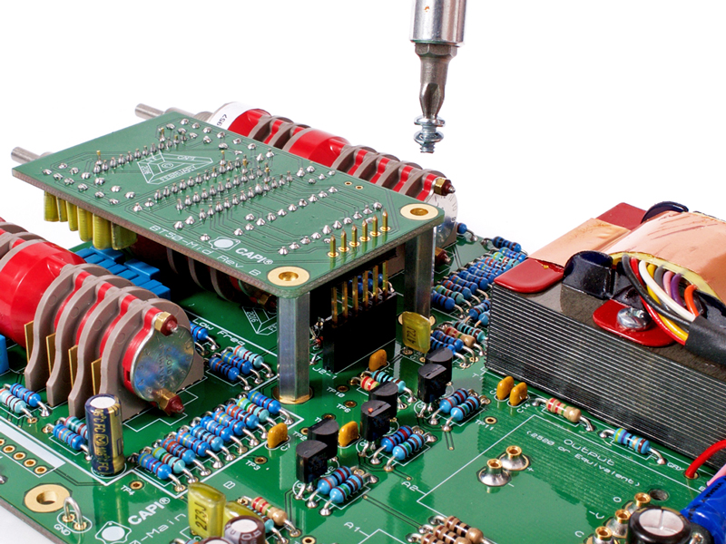
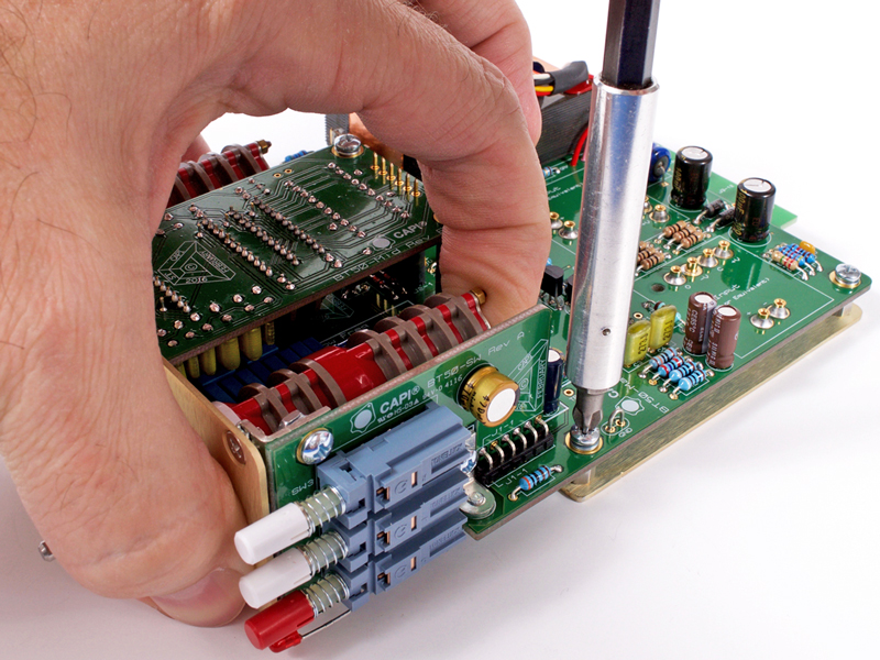
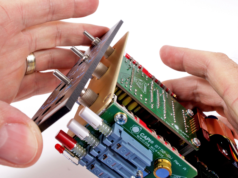
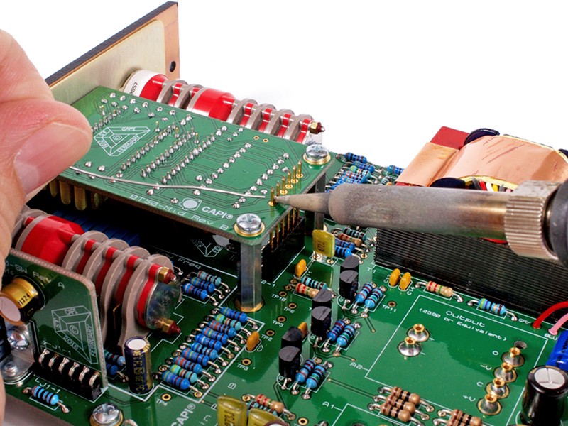
6.5 |
Slip the mid-band PCB assembly over the 6-pin gold header and secure with 3/16" pan head screws and lockwashers.
Lightly snug them but do not fully tighten yet.
|
|
Click to enlarge
|
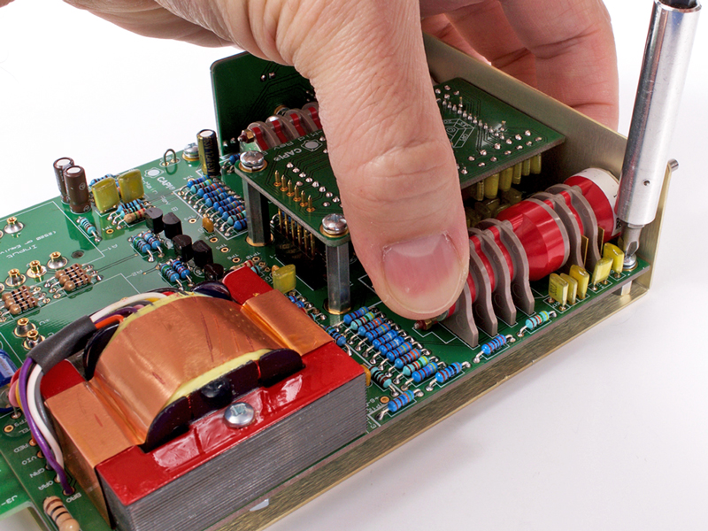
6.6 |
Insert the switch PCB assembly into position and secure with a 3/16" pan head screw and lockwasher. Lightly snug it
but do not fully tighten yet.
|
|
Click to enlarge
|
6.7 |
Insert the LED into the switch PCB and align with the center of the pushbutton switch caps. Clip the leads so they are
1/16" or a little more below the bottom of the PCB. This must be done now as there will be no access later without
complete disassembly. DO NOT solder the LED at this time!
|
|
Click to enlarge
|
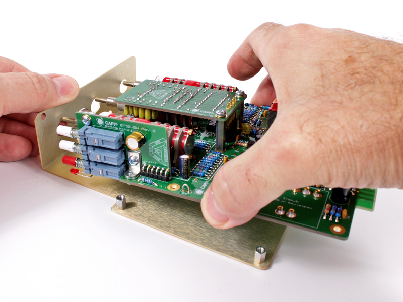
6.8 |
Slip the entire assembly into position in the L-Bracket.
|
|
Click to enlarge
|
6.9 |
Lightly snug the four pan head screws and lockwashers to the standoffs. DO NOT fully tighten at this time.
|
|
Click to enlarge
|
6.10 |
Slip the #4 outside tooth lockwasher between the L-Bracket and Keystone bracket of the switch PCB. Install a 3/16"
undercut flat head screw but DO NOT fully tighten at this time.
|
|
Click to enlarge
|
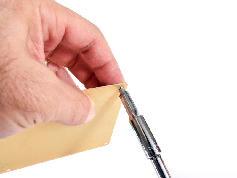
6.11 |
Fully secure the flat head screw while tightly holding the Keystone bracket to the switch PCB with needle nose pliers.
This will keep the Keystone bracket from turning and throwing the switch PCB out of alignment.
|
|
Click to enlarge
|
6.12 |
Pinch the Low Freq Grayhill tight to the L-Bracket and fully tighten the front mounting screw.
|
|
Click to enlarge
|
6.13 |
Pinch the Hi Freq Grayhill tight to the L-Bracket and fully tighten the front mounting screw.
|
|
|
6.14 |
Tighten both rear mounting screws.
|
|
Click to enlarge
|
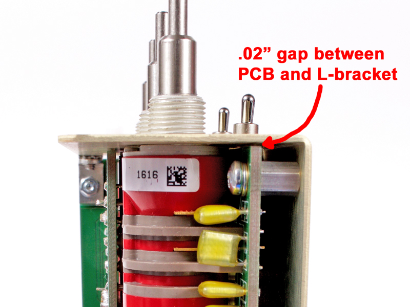
6.15 |
By design, the front mounting plate of the Grayhill switches will touch the L-Bracket while the PCB will be gapped away by
.02".
|
|

Click to enlarge
|
6.16 |
Slip faceplate into position making sure to guide LED as required.
|
|
Click to enlarge
|
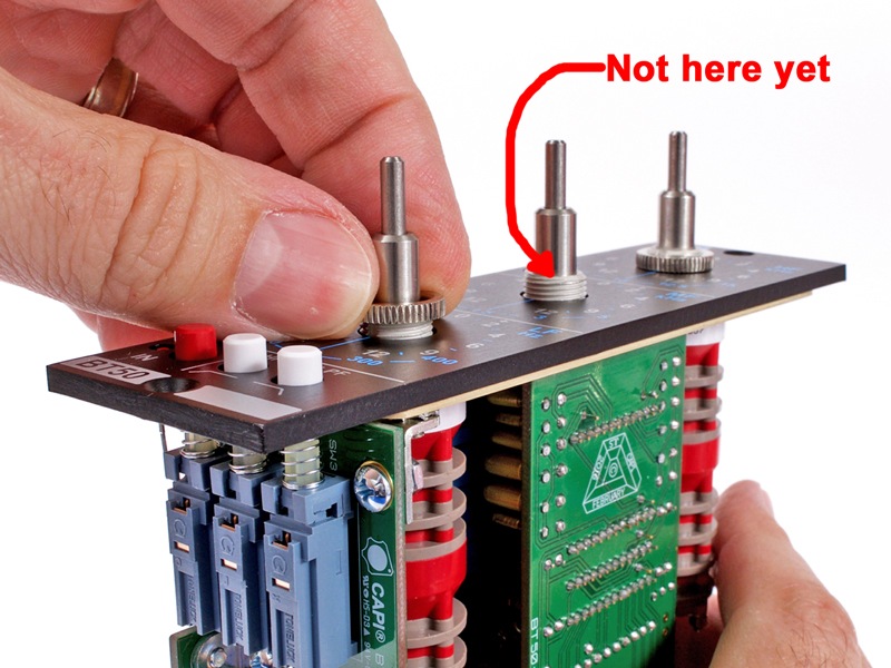
6.17 |
Finger tight snug knurled nuts onto HF and LF Grayhill switches. Make sure faceplate stays parallel to L-Bracket.
|
|
Click to enlarge
|
6.18 |
Make sure both screws and lockwashers are slightly making contact with mid-band PCB but are still not fully tightened yet.
|
|
Click to enlarge
|
6.19 |
Install and finger tight snug MF knurled nut.
|
|
Click to enlarge
|
6.20 |
Fully tighten mounting screws to mid-band PCB.
|
|
Click to enlarge
|
6.21 |
Check the three pushbutton switch caps for proper alignment in the faceplate. Make sure the switch PCB is not skewed or
crooked and fully tighten the 3/16" screw from the bottom of the main PCB into the Keystone bracket.
|
|
Click to enlarge
|
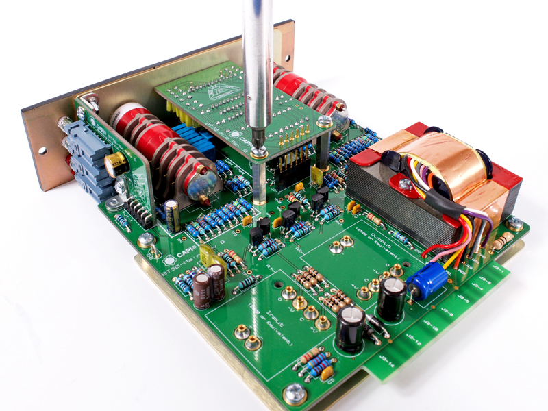
6.22 |
With a screwdriver and 3/16" wrench, tighten the hardware on the top Keystone bracket.
|
|
Click to enlarge
|
6.23 |
Tighten the hardware on the lower Keystone bracket.
|
|

Click to enlarge
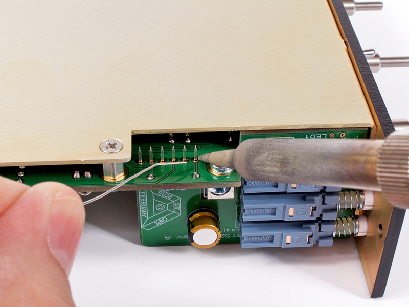
|
6.24 |
Solder the six pins of the 90° header to the main PCB.
|
|
Click to enlarge
|
6.25 |
Make sure the LED is fully seated to the faceplate and solder the leads to the top of the switch PCB.
|
|

Click to enlarge
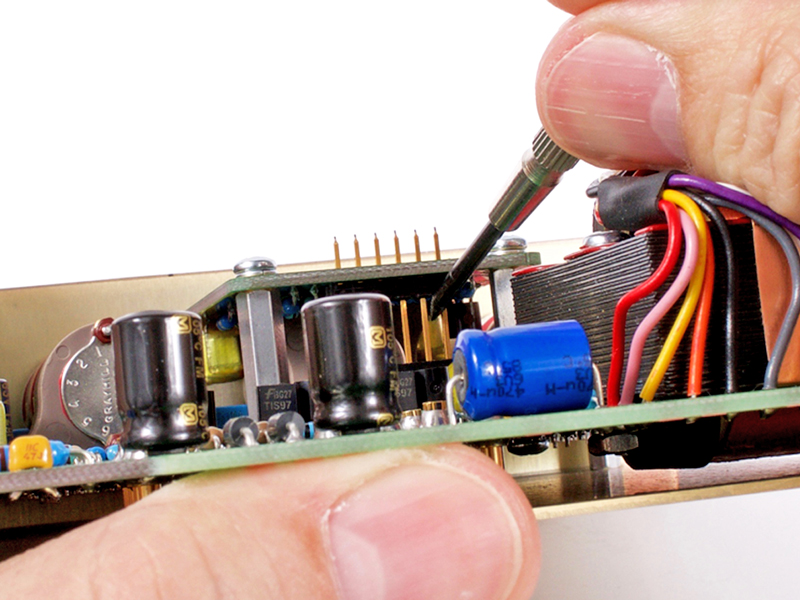
|
6.26 |
Use a screwdriver or similar to make sure the 6-pin gold header is tightly seated against the mid-band PCB.
|
|
Click to enlarge
|
6.27 |
Solder the six pins.
|
|
Click to enlarge
|
6.28 |
Trim the six pins.
|
|

Click to enlarge
|
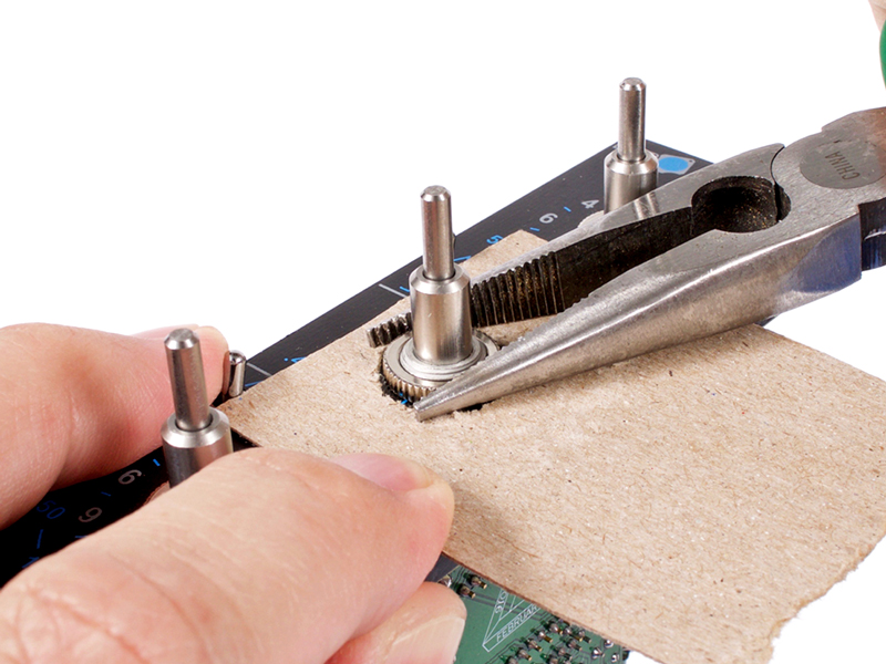
6.29 |
Using a needle nose pliers and something to protect the faceplate (I use a thin piece of cardboard), tighten all three
knurled nuts.
|
|

Click to enlarge
|
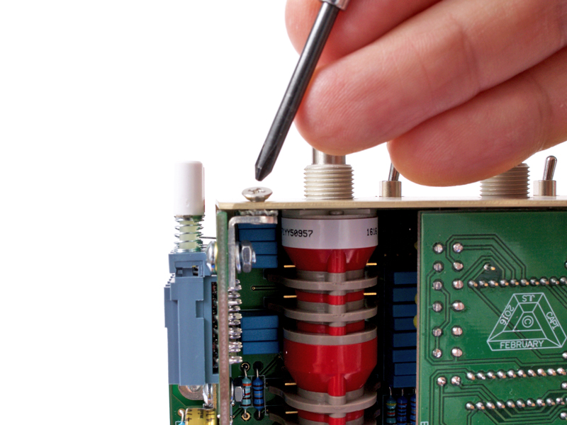
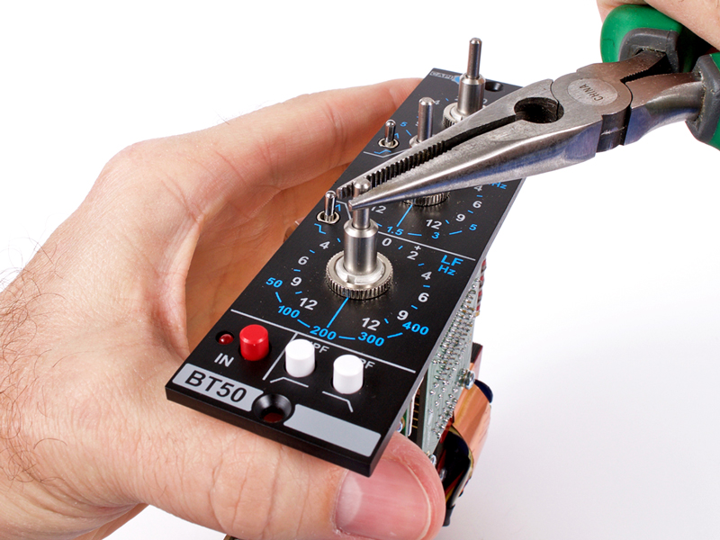
6.30 |
Using your needle nose pliers, turn each cut/boost shaft 5 clicks clockwise. The factory position is -12 so this will put
them all to 0.
|
|
Click to enlarge
|
6.31 |
Turn each frequency select shaft 2 clicks clockwise. This will put them to their respective center frequency.
|
|
Click to enlarge
|
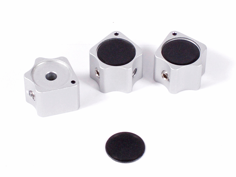
6.32 |
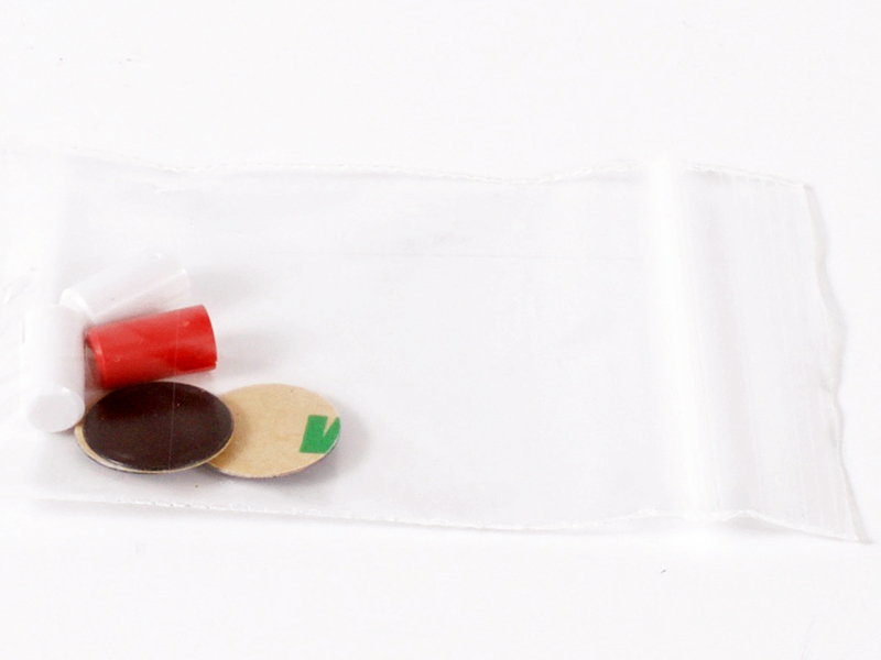
Locate and install the black knob inserts.
|
|

Click to enlarge
|
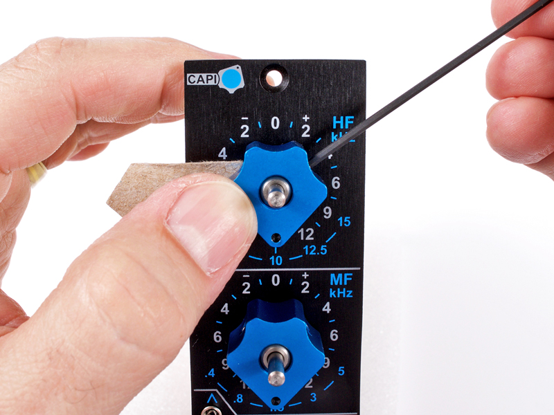
6.33a |
Using a thin piece of cardboard or similar as a spacer, begin installing the blue frequency control knobs from the low
band to hi band. The spacer is required to keep the knobs from dragging and rubbing on the faceplate.
|
Click to enlarge
|
6.33b |
Something around .02" thick works perfectly.
|
|
Click to enlarge
|
6.34a |
I recommend two layers of the .02" thick spacer under the clear cut/boost knobs.
|
Click to enlarge
|
6.34b |
Install the knobs from the hi band to low band.
|
|
The contents of this assembly guide page, including but not limited to all text, photographs and diagrams, is the
intellectual property of Classic Audio Products, Inc. Reproduction or re-publication by any means whatsoever, whether
electronic, mechanical or electro-mechanical, is strictly prohibited under International Copyright laws. The sole purpose
for this document is to aid in the assembly of the BT50 Rev B kit offered by Classic Audio Products, Inc.
Commercial use is prohibited.
|
 |
|
Classic Audio Products, Inc. is a DIY parts / kit retailer and provides no direct support for any of the products
available on this site. Support for the kits can be found at the respective [Build] thread at groupdiy.com. Any support
Classic Audio Products, Inc. chooses to provide, is provided "as is" without warranty of any kind. We cannot offer
any guarantee as to the consequences of the support provided. Should the support cause damage or loss of any kind, Classic
Audio Products, Inc. shall not be held liable to you or any other person for indirect, special, punitive, incidental, or
consequential damages or losses. While the successful build rate is extremely high, there is no guaranteed favorable
outcome. Always research and plan any project you undertake thoroughly. Sometimes, a project is over your head, and it
just makes more sense to hire a qualified professional.
|
|
 |
| |
|
|
|
| 0 items |
|
|
|
 |
Curative Notice |
|
|
| Classic Audio Products, Inc. is not affiliated with API.
Customers and fans should not refer to Classic Audio Products, Inc. as "Classic API."
API is a registered trademark of Automated Processes Incorporated. Classic Audio Products, Inc. has no affiliation with
Automated Processes Incorporated. |
|
|
|
|
Bestsellers |
|
|
|
Manufacturers |
|
|
|
Quick Find |
|
|
|
|
|
|
|


 Preface


")