|
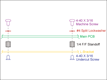
| LC25-T LC40-T Rev A Pictorial Build Guide |
 |
|
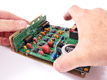
 |
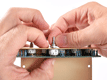
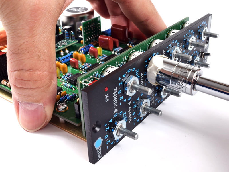
|
MAKE SURE the build guide you follow matches the Revision of the PCB you are building!
|
Click to enlarge
|
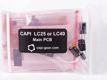
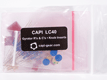
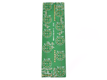
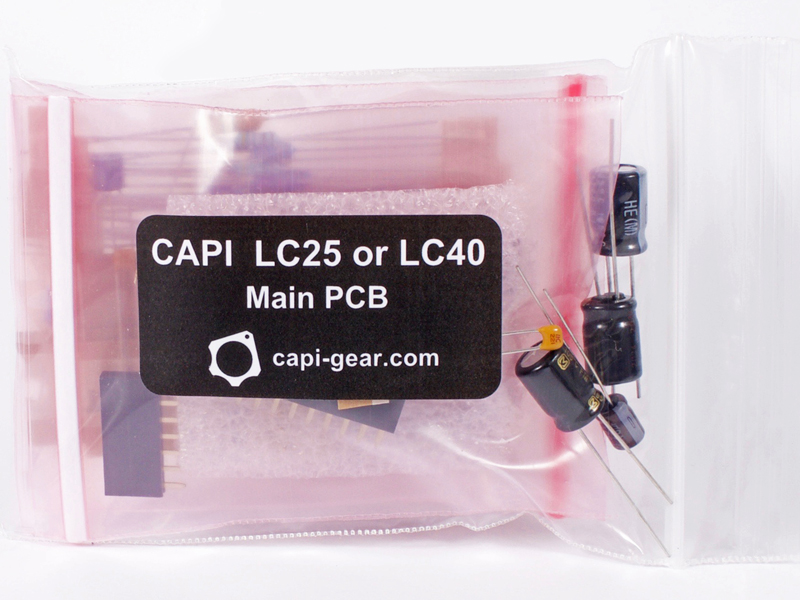
2.A.0 |
The follow parts can be found in the Main PCB bag.
|
 |
Click to enlarge
|
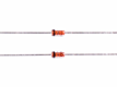
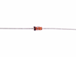
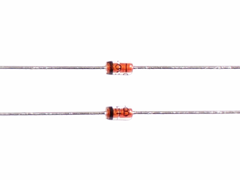
2.A.1 |
Fairchild 1N914 diode, label is "91 4B"
|
Click to enlarge
|
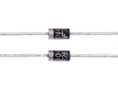
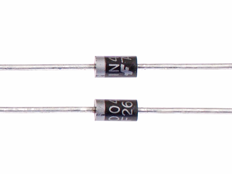
2.A.2 |
Fairchild 1N4004 diode, label is "1N4004"
|
Click to enlarge
|
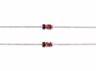
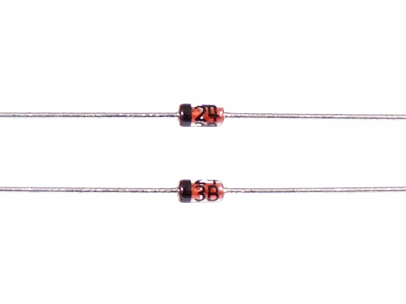
2.A.3 |
Fairchild 13V zener diode, label is "24 3B"
|
Click to enlarge
|
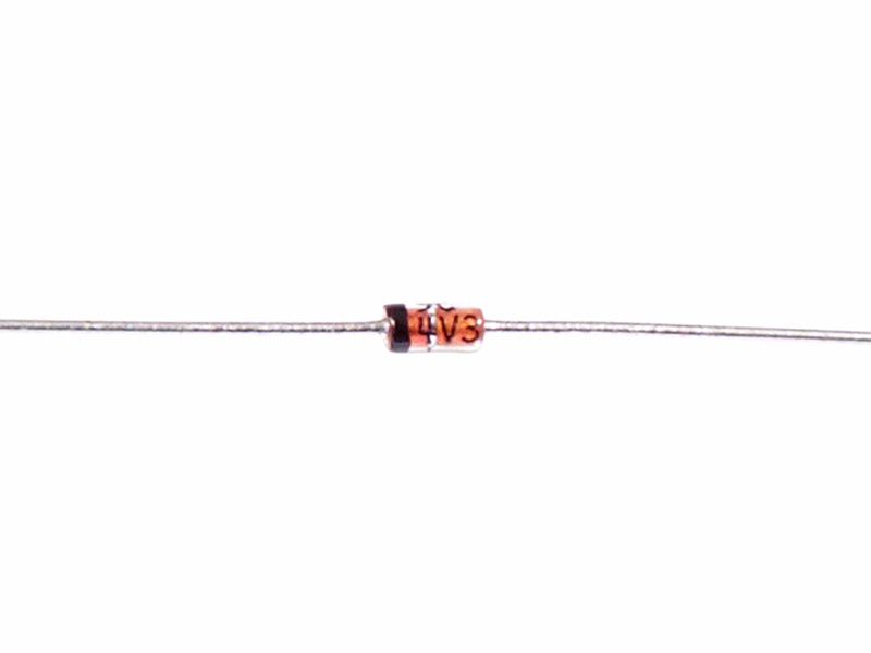
2.A.4 |
Fairchild 4V3 zener diode, label is "4V3"
|
Click to enlarge
|
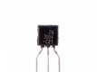
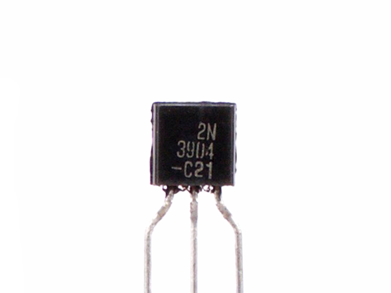
2.A.5 |
Fairchild 2N3904 transistor, label is "2N 3904"
|
|

Click to enlarge
|
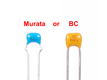
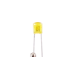
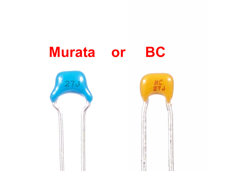
2.A.6 |
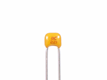
Murata or BC 27pF ceramic capacitor, label is "27J" or "BC 27J"
|
Click to enlarge
|
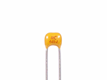
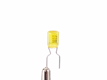
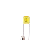
2.A.7 |
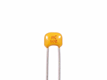
BC 68pF ceramic capacitor, label is "BC 68J"
|
Click to enlarge
|
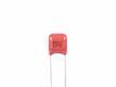
2.A.8 |
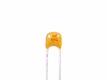
Murata or BC 82pF ceramic capacitor, label is "82J" or "BC 82J"
|
Click to enlarge
|
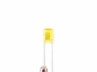
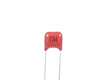
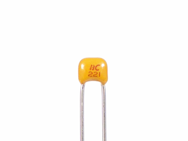
2.A.9 |
BC 220pF ceramic capacitor, label is "BC 221"
|
Click to enlarge
|
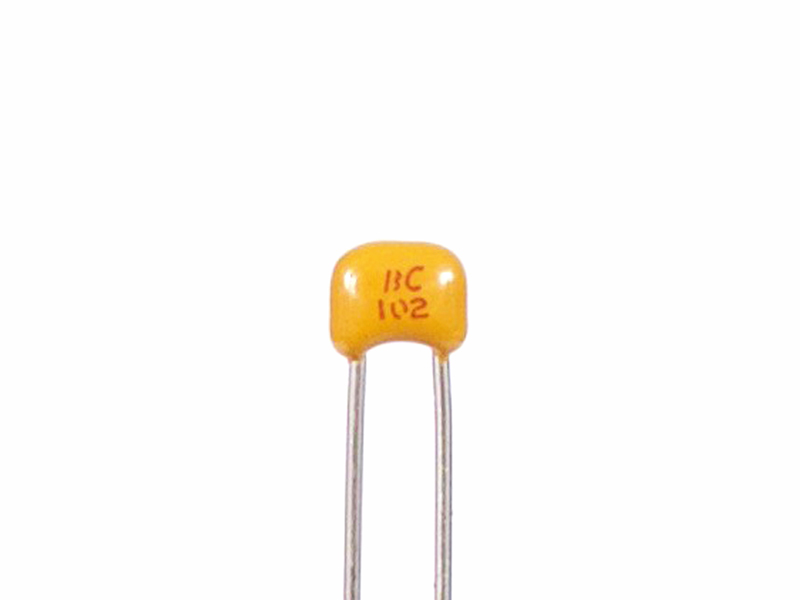
2.A.10 |
BC 1000pF ceramic capacitor, label is "BC 102"
|
Click to enlarge
|
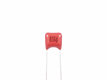
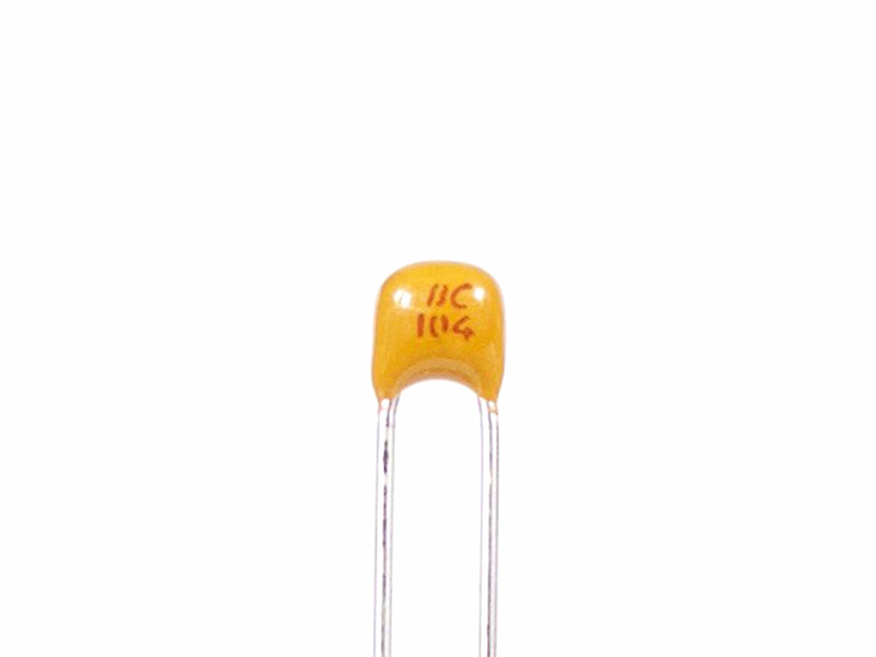
2.A.11 |
BC .1μF ceramic capacitor, label is "BC 104"
|
Click to enlarge
|
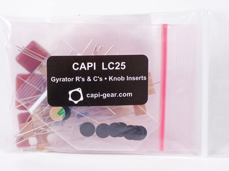
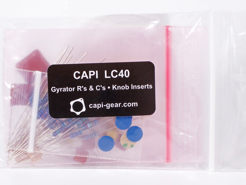
2.B.0 |
The follow capacitors can be found in the LC25 Gyrator R's and C's ~ Inserts bag.
|
|
Click to enlarge
|
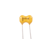
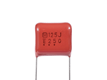
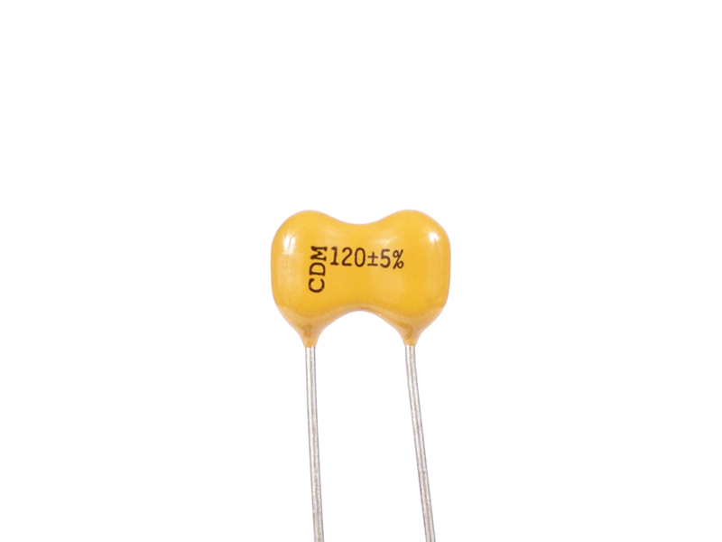
2.B.1 |
Cornell Dubilier 120pF mica capacitor, label is "CDM 120"
|
Click to enlarge
|
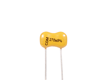
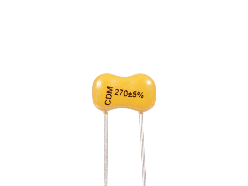
2.B.2 |
Cornell Dubilier 270pF mica capacitor, label is "CDM 270"
|
|
Click to enlarge
|
2.B.3 |
Nichicon .001μF film capacitor, label is "102J"
|
Click to enlarge
|
2.B.4 |
Nichicon .0015μF film capacitor, label is "152J"
|
Click to enlarge
|
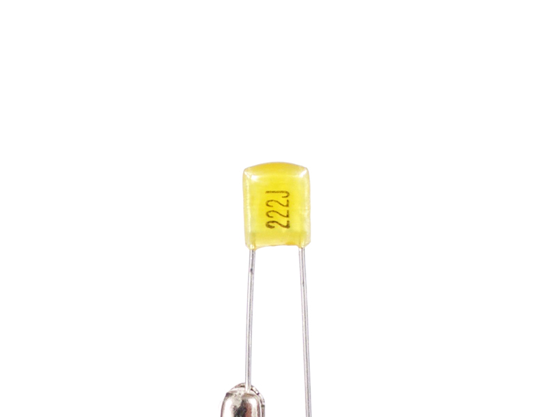
2.B.5 |
Nichicon .0022μF film capacitor, label is "222J"
|
Click to enlarge
|
2.B.6 |
Nichicon .0047μF film capacitor, label is "472J"
|
|
Click to enlarge
|
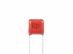
2.B.7 |
Panasonic .01μF film capacitor, label is "103J"
|
Click to enlarge
|
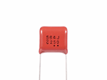
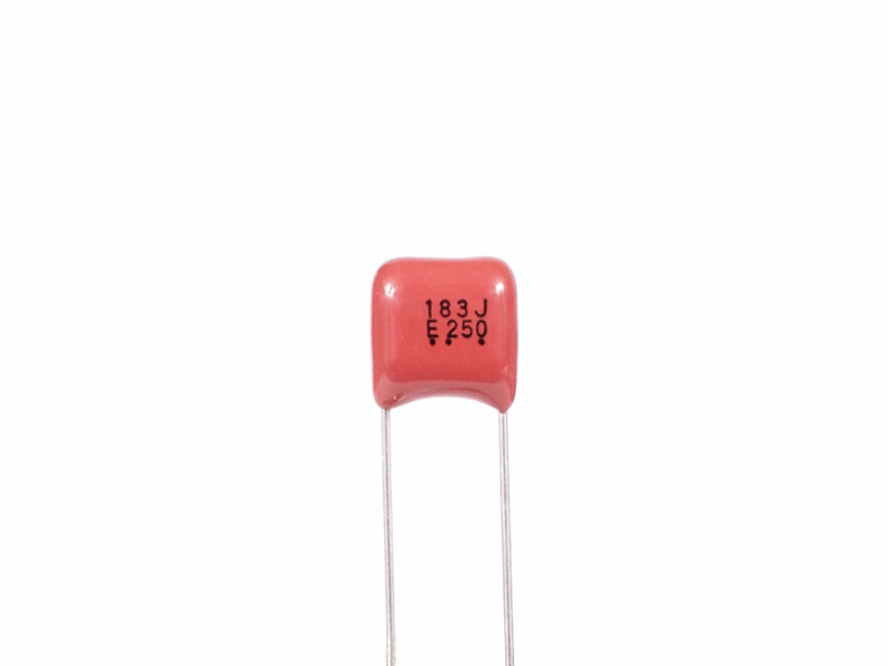
2.B.8 |
Panasonic .018μF film capacitor, label is "183J"
|
Click to enlarge
|
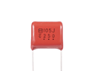
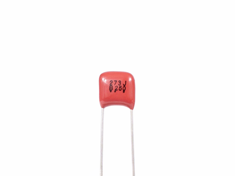
2.B.9 |
Panasonic .027μF film capacitor, label is "273J"
|
Click to enlarge
|
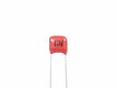
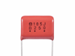
2.B.10 |
Panasonic .033μF film capacitor, label is "333J"
|
Click to enlarge
|
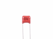
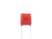
2.B.11 |
Panasonic .068μF film capacitor, label is "683J"
|
Click to enlarge
|
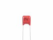
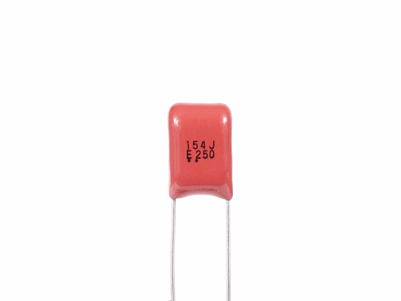
2.B.12 |
Panasonic .15μF film capacitor, label is "154J"
|
Click to enlarge
|
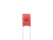
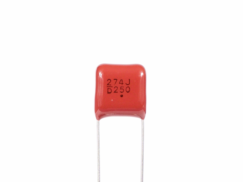
2.B.13 |
Panasonic .27μF film capacitor, label is "274J"
|
Click to enlarge
|
2.B.14 |
Panasonic .56μF film capacitor, label is "564J"
|
Click to enlarge
|
2.B.15 |
Panasonic 1μF film capacitor, label is "105J"
|
Click to enlarge
|
2.B.16 |
Panasonic 1.8μF film capacitor, label is "185J"
|
Click to enlarge
|
2.C.0 |
The follow capacitors can be found in the LC40 Gyrator R's and C's ~ Inserts bag.
|
|
Click to enlarge
|
2.C.1 |
Cornell Dubilier 120pF mica capacitor, label is "CDM 120"
|
Click to enlarge
|
2.C.2 |
Cornell Dubilier 270pF mica capacitor, label is "CDM 270"
|
|
Click to enlarge
|
2.C.3 |
Nichicon .001μF film capacitor, label is "102J"
|
Click to enlarge
|
2.C.4 |
Nichicon .0015μF film capacitor, label is "152J"
|
Click to enlarge
|
2.C.5 |
Nichicon .0022μF film capacitor, label is "222J"
|

Click to enlarge
|
2.C.6 |
Nichicon .0027μF film capacitor, label is "272J"
|
Click to enlarge
|
2.C.7 |
Nichicon .0047μF film capacitor, label is "472J"
|

Click to enlarge
|
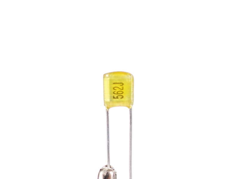
2.C.8 |
Nichicon .0056μF film capacitor, label is "562J"
|
|
Click to enlarge
|
2.C.9 |
Panasonic .01μF film capacitor, label is "103J"
|
Click to enlarge
|
2.C.10 |
Panasonic .018μF film capacitor, label is "183J"
|
Click to enlarge
|
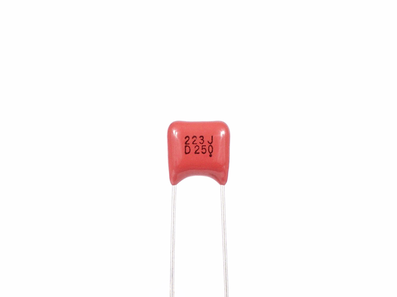
2.C.11 |
Panasonic .022μF film capacitor, label is "223J"
|
Click to enlarge
|
2.C.12 |
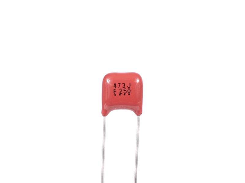
Panasonic .047μF film capacitor, label is "473J"
|
Click to enlarge
|
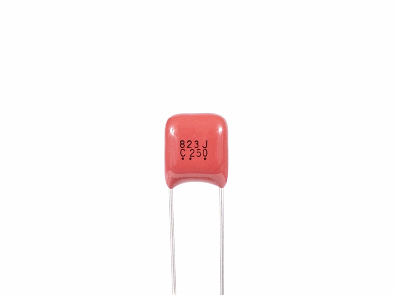
2.C.13 |
Panasonic .082μF film capacitor, label is "823J"
|
Click to enlarge
|
2.C.14 |
Panasonic .15μF film capacitor, label is "154J"
|
Click to enlarge
|
2.C.15 |
Panasonic .33μF film capacitor, label is "334J"
|
Click to enlarge
|
2.C.16 |
Panasonic .56μF film capacitor, label is "564J"
|
Click to enlarge
|
2.C.17 |
Panasonic 1.2μF film capacitor, label is "125J"
|
Click to enlarge
|
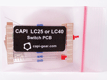
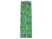
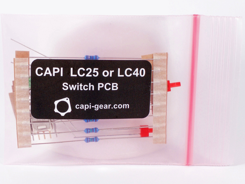
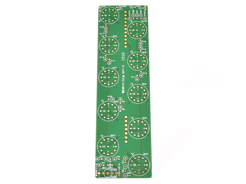
2.D.0 |
Contains all parts for the switch PCB excluding the Grayhill switches.
|
|
Click to enlarge
|
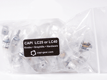
2.D.1 |
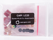
Contains the hardware bag, all Grahill switches and CAPI® control knobs.
|

Click to Go There
|
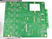
3.0 |
The first task is to build the DTO5 opamp. Please visit the
DTO5 build page and then return here.
|
|
Click to enlarge
|
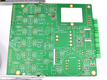
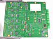
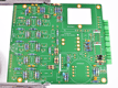
3.0a |
And we begin with a blank canvas.
|
|
Click to enlarge
|
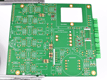
3.1 |
Identify and install the small package diodes.
|
|
Click to enlarge
|
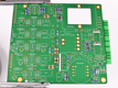
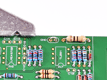
3.2 |
Locate and install all of the 10Ω power damping R's designated with PR.
|
|
Click to enlarge
|
3.3 |
Identify and install all 1% .25W R's for the Main and RR sections of the PCB.
**Please note: the value of RR8 was not determined at the early part of this build so it is not installed in the
build pics.
**Also note: RR1 was 59k in all of the build pics but was later changed to 100k when I finetuned RR8.
The values shown in the BOM are correct for both RR1 and RR8.
|
|
Click to enlarge
|
3.4 |
Identify and install all gyrator R's. These are designated GR on the PCB.
|
|
Click to enlarge
|
3.5 |
Install the large package diodes and the .5W R's. Save a cutoff lead from a diode for the next step.
|
|
Click to enlarge
|
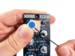
3.6 |
Bend the saved lead from step 5 over a small screwdriver tip and solder into the GND position. This is the preferred probe
hook location for testing.
|
|
Click to enlarge
|
3.7 |
Identify and install the small package ceramic capacitors.
|
|
Click to enlarge
|
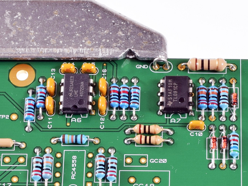
3.8 |
Identify and install the LME and TL0 opamps.
|
|
Click to enlarge
|
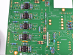
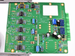
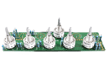
3.9 |
Identify and install the five 4558 gyrator opamps.
|
|

Click to enlarge
|
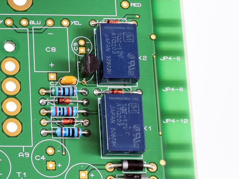
3.10 |
Install the two relays and then the 2N3904 transistor.
|
|
Click to enlarge
|
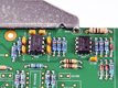
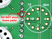
3.10a |
Be extra careful not to short the close via to the adjacent 2N3904 pad!
|
|
Click to enlarge
|
3.11 |
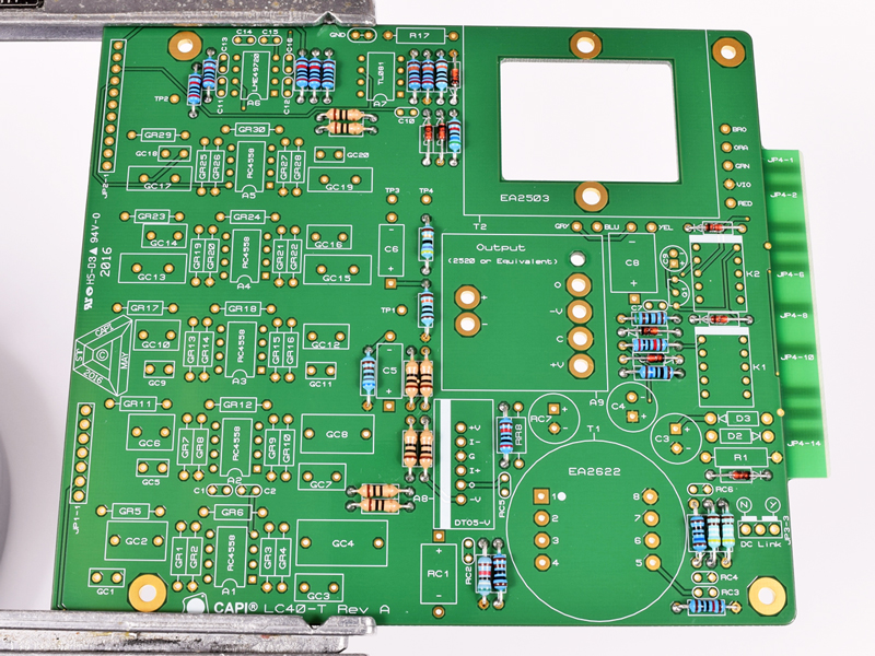
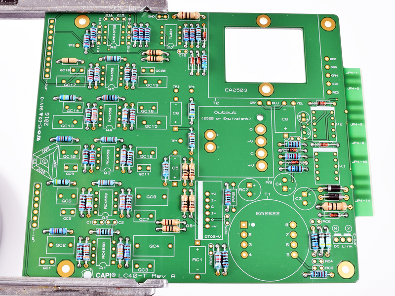
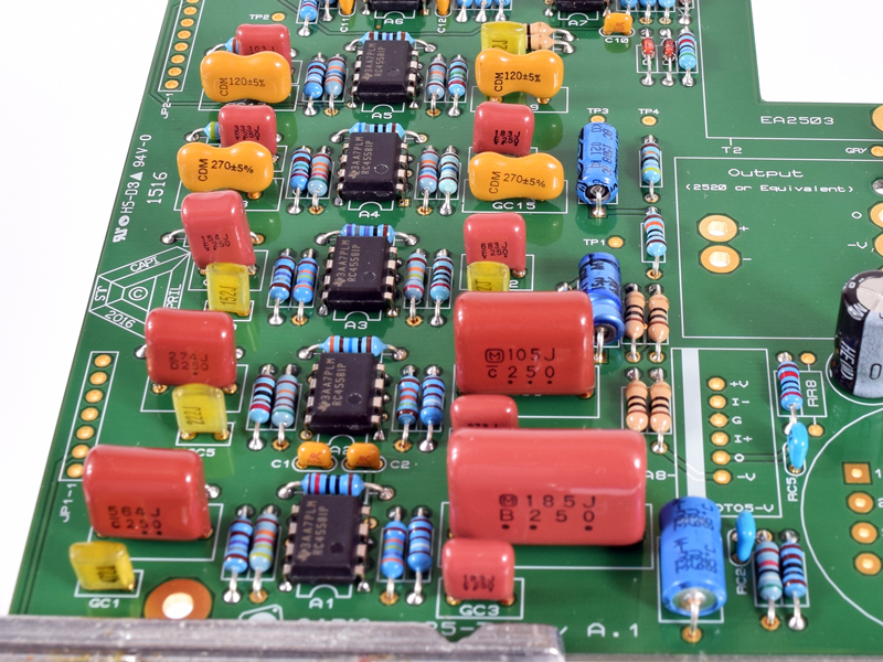
Identify and install all remaining capacitors for the Main and RR sections of the PCB.
|
|
|
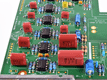
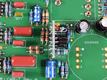
3.12 |
Identify and install all gyrator capacitors for your specific build. These are designated GC. I changed my normal stuffing
order in the four below pics to provide a better photo op.
|
|
Click to enlarge
|
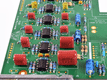
3.12a |
LC25 with half of the gyrator C's installed.
|
|

Click to enlarge
|
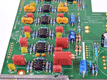
3.12b |
LC25 with all of the gyrator C's installed.
|
|
Click to enlarge
|
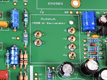
3.12c |
LC40 with half of the gyrator C's installed.
|
|
Click to enlarge
|
3.12d |
LC40 with all of the gyrator C's installed.
|
|

Click to enlarge
|
3.13 |
Install the 3-pin DC-Link shunt jumper header as well as the 7 and 11-pin receptacles that mate to the switch PCB. The
3-pin header and shunt can be found in the small hardware bag, which is inside the bag with the knobs and Grayhills.
|
|
Click to enlarge
|
3.14 |
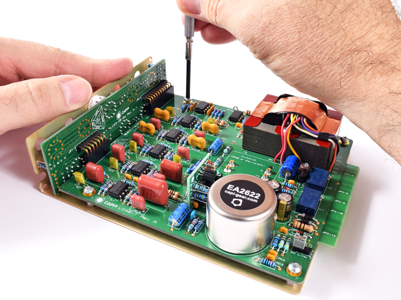
Install the six opamp sockets for A9. These should be installed thru and only soldered at the bottom of the PCB. The
solder seen at the top has leaked thru during the process.
|
|
Click to enlarge
|
3.15 |
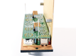
Install the DTO5 opamp making sure it sits perpendicular to the main PCB.
|
|
Click to enlarge
|
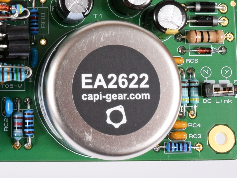
3.16 |
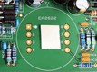
Prep for install of the EA2622 transformer. This step can be improvised. I use a small piece of foam tape that is only
stuck to the PCB not the transformer. The goal is to slightly elevate the bottom of the can so it does not short with any
of the pads. Foam tape is not included with the kit.
|
|

Click to enlarge
|
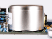
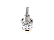
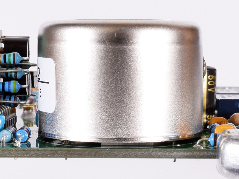
3.16a |
Install the EA2622.
|
|
Click to enlarge
|
3.16b |
Try and maintain an approximate 0.03" space between the bottom of the can and the PCB.
|
|
Click to enlarge
|
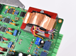
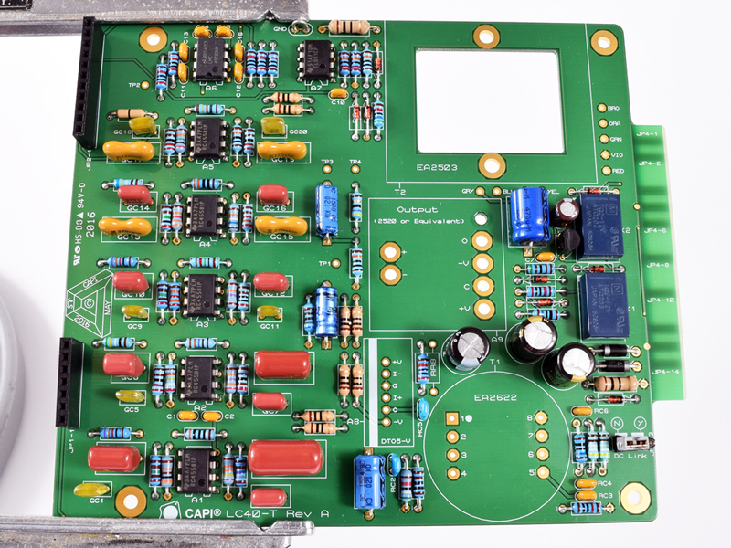
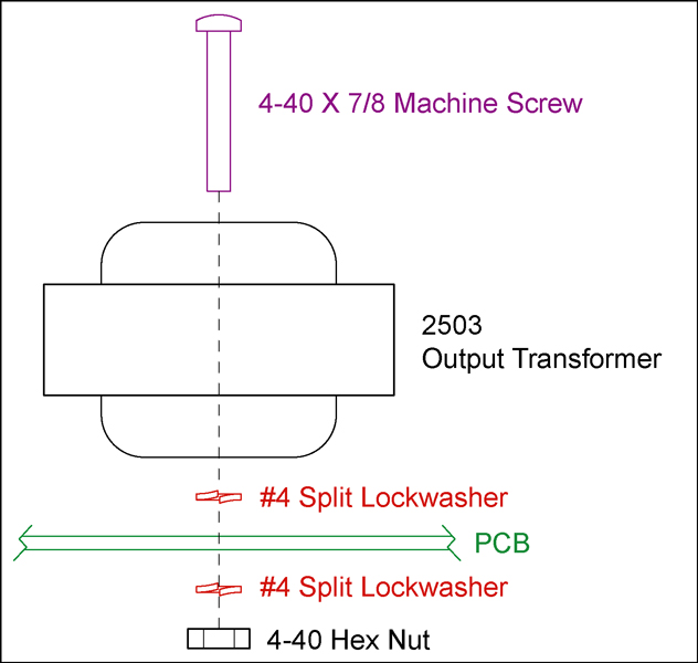
3.17 |
Install the 2503 style output transformer following the
2503 hardware guide.
I used the Litz version for these builds so I had to alter the lead's color code placement. For the Litz version, you
can use this pic as a reference or follow the chart on the bottom left of the
datasheet. For a standard EA2503, just match the lead's colors to their respective holes.
|
Click to enlarge
|
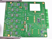
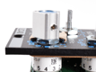
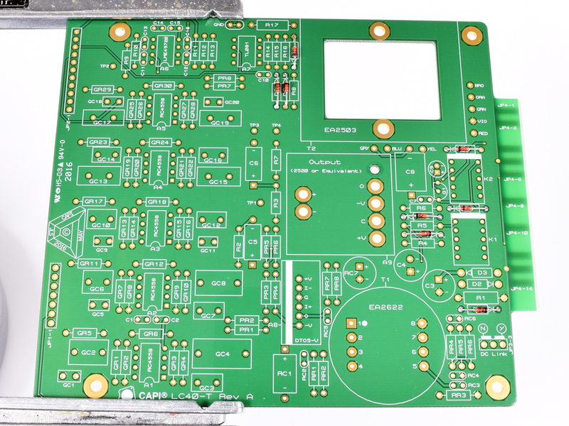
4.0 |
And we again begin with a blank canvas.
|
|
Click to enlarge
|
4.1 |
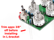
a. Install the 1N914 diode. Remember the black band on the diode goes to the PCB hole that the silkscreen
arrow is pointing to. Bending the lead over a small screwdriver or probe tip is recommended.
b. Install all resistors. The bend cannot be too high or the lead may interfere with the L-bracket once you
get to final assembly.
|
|
Click to enlarge
|
4.2 |
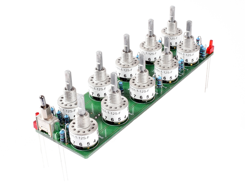
Locate the ten Grayhill 56 series switches. Remove the nuts and put them to the side. Discard the lockwashers as we do not
use them. The stop-pin has been factory set between positions 1 and 12.
|
|
Click to enlarge
|
4.3 |
Loose fit the following six switches with no solder. SW3, 5, 6, 7, 9 and 11. Make sure the pin numbers on the
switch's label sticker properly correspond to the silkscreen labels on the PCB.
|
|
Click to enlarge
|
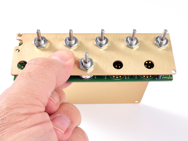
4.4 |
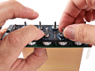
Carefully slide the switch PCB into the L-bracket. Make sure each and every switch's small collar fits evenly inside
the corresponding hole in the L-bracket. Begin to install the panel nuts while continually holding the PCB in place.
Finger tight for the nuts is fine for now.
|
|

Click to enlarge
|
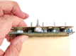
4.5 |
Install the remaining five panel nuts while continuing to pinch the PCB in place.
|
|
Click to enlarge
|
4.6 |
Double check to make sure all six switches are flat and fully seated against the L-bracket.
|
|
Click to enlarge
|
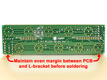
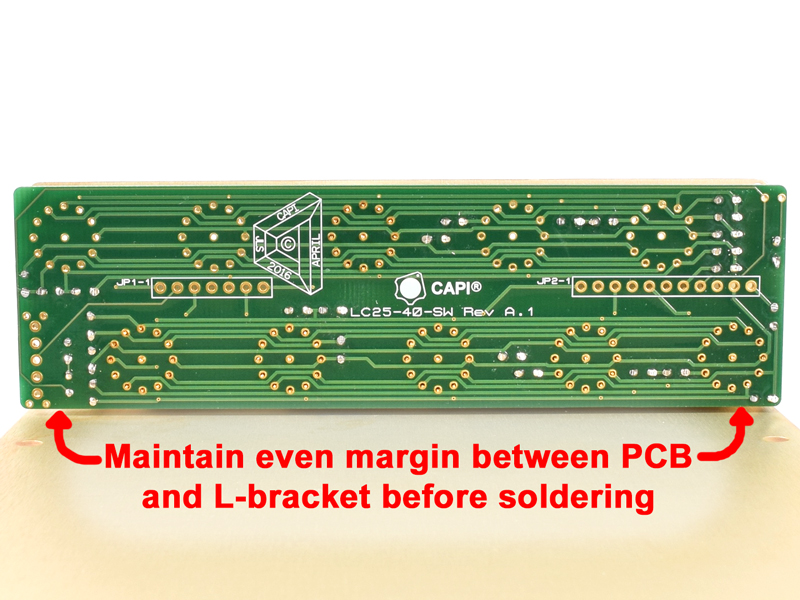
4.7 |
Before soldering, make sure the PCB is sitting parallel to L-bracket. The margin should be 0.03". Adjust as needed.
|
|

Click to enlarge
|
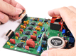
4.8 |
Stand assembly up on the switch shafts. Solder two pins on each switch making sure the PCB is fully seated.
|
|
|
4.9 |
a. Finish soldering the rest of the switch pins while the assembly is still standing upwards. Alternating
between switches is recommended to not overheat any of their innards.
b. Continue to leave the switch PCB fastened to the L-bracket.
|
|

Click to enlarge
|
4.10 |
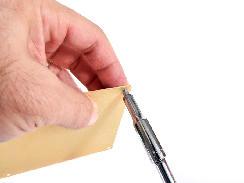
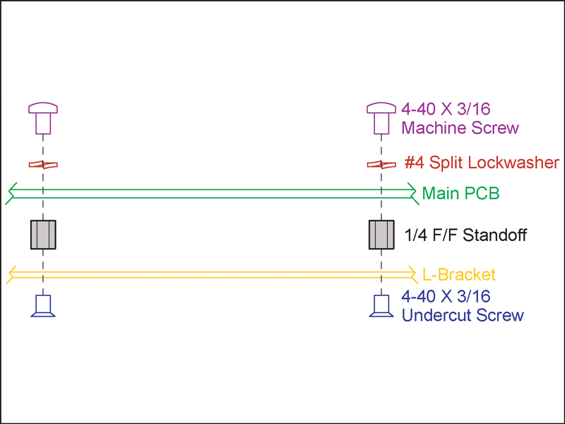
Install the four standoffs to the L-bracket with 3/16" undercut flat head screws. I use a nut driver on the standoffs
which typically works so well that a screwdriver is not needed.
|
|
Click to enlarge
|
4.11 |
Carefully insert the 90° headers into their respective receptacles orientated as shown.
|
|
Click to enlarge
|
4.12 |
Gently slide the main PCB assembly into position on the L-bracket guiding the 90° header pins into their holes of the
switch PCB.
|
|
Click to enlarge
|
4.13 |
Install the four 3/16" pan head screws into the standoffs. Lockwashers are not needed at this time since its only
temporary. The PCB hole size for these screws is very small so there should be little to no play or movement.
|
|
Click to enlarge
|
4.14 |
Push the 90° headers against the switch PCB to make sure they are aligned properly and tight to the board.
|
|

Click to enlarge
|
4.15 |
Carefully reach inside and solder two pins of each header at the top side of the switch PCB. A long narrow tip is required
for this. Other methods can be used to properly install these headers but I have found this to be the easiest.
|
|
|
4.16 |
Break down the entire assembly by removing the six Grayhill nuts and the four 3/16" mounting screws. Gently unplug the
switch PCB from the main PCB.
|
|
Click to enlarge
|
4.17 |
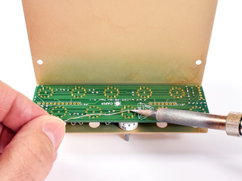
Solder the remaining header pins at the top of the switch PCB.
|
|
Click to enlarge
|
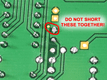
4.18 |
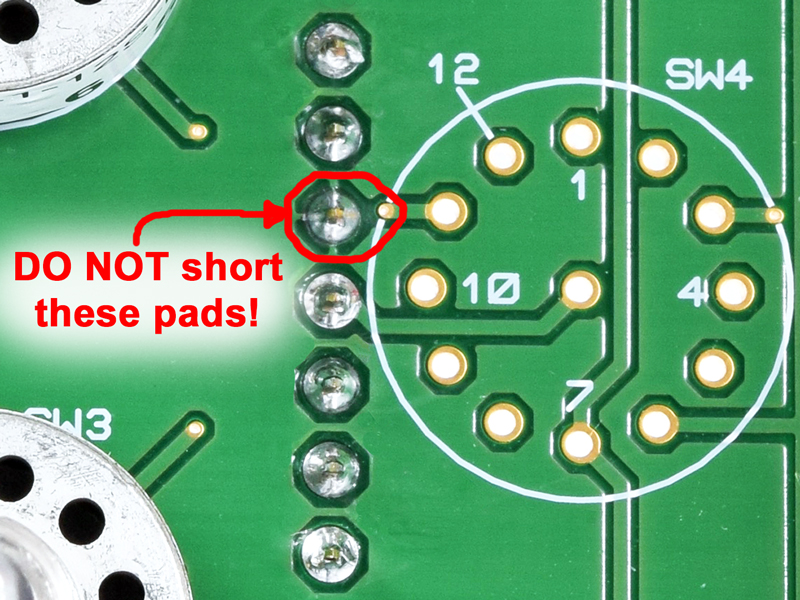
Make sure not to bridge the via to the adjacent header pin near SW4!
|
|

Click to enlarge
|
4.19 |
a. Insert the four remaining Grayhill switches into their locations with no solder.
b. Insert the C&K toggle switch into the PCB with no solder. It is imperative that the flat of the
switch bushing be properly orientated to the flat markings shown in the silkscreen.
c. Insert the three LED's into their locations with no solder. The silkscreen arrow points to the
shorter cathode lead.
|
|
Click to enlarge
|
4.20 |
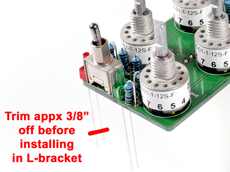
Cut off approximately 3/8" of an inch from the leads of the Red BYPass LED.
|
|
|
4.21 |
Carefully insert the switch PCB assembly into the L-Bracket. Make sure the Grayhill switches fully seat into their
mounting holes.
|
|
Click to enlarge
|
4.22 |
a. Slip the faceplate into position.
b. Finger snug panel nuts on the four unsoldered Grayhill switches as well as two or three on the other side
of the faceplate.
|
|
Click to enlarge
|
4.23 |
a. Turn the assembly over and stand on the switch shafts.
b. The toggle switch should remain tight to the PCB and NOT fall against the L-Bracket.
c. Make sure all three LED's fall down and sit tight to the L-Bracket.
|
|
|
4.24 |
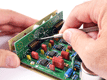
Solder all remaining pins and leads for the switch PCB.
|
|
5.1 |
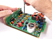
Remove the switch nuts and disassemble the faceplate, L-Bracket and switch PCB.
|
|
|
5.2 |
Carefully plug the switch PCB into the main PCB.
|
|
|
5.3 |
Slide the entire PCB assembly into position on the L-Bracket for (hopefully) the last time.
|
|
Click to enlarge
|
5.4 |
Secure the main PCB to the L-Bracket with the four 3/16" pan head screws. This time utilize the lockwashers.
|
|

Click to enlarge
|
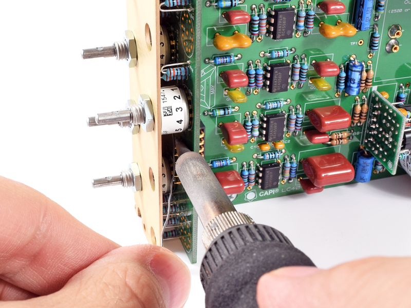
5.5 |
Slip the faceplate into position and secure with the ten Grayhill panel nuts. Use a 10mm socket and don't forget about
console tape on the socket to prevent scratching up the faceplate!
|
|
|
5.6 |
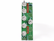
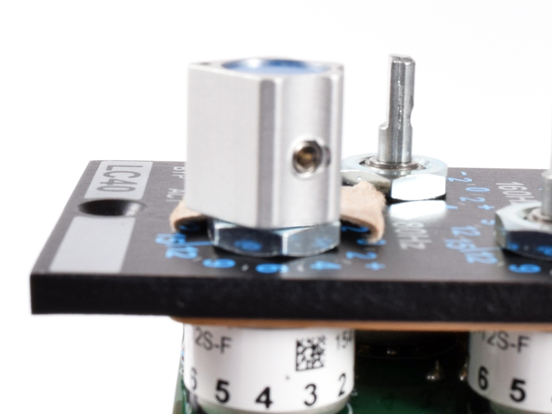
Install the colored inserts on the ten CAPI control knobs.
|
|
Click to enlarge
|
5.7a |
Using a thin piece of cardboard or similar as a spacer, begin installing the control knobs from the lowest frequency to
the highest. The spacer is required to keep the knobs from dragging and rubbing on the panel nuts. Something around
.02" thick works perfectly.
|
|
Click to enlarge
|
5.7b |
Since we have not turned the switch shafts (you didn't did you?!), they will all be factory set in the -15dB position.
Align the knobs accordingly and tighten with a .05" hex key.
|
|
The contents of this assembly guide page, including but not limited to all text, photographs and diagrams, is the
intellectual property of Classic Audio Products, Inc. Reproduction or re-publication by any means whatsoever, whether
electronic, mechanical or electro-mechanical, is strictly prohibited under International Copyright laws. The sole purpose
for this document is to aid in the assembly of the LC25-T LC40-T Rev A kit offered by Classic Audio Products, Inc.
Commercial use is prohibited.
|
 |
|
Classic Audio Products, Inc. is a DIY parts / kit retailer and provides no direct support for any of the products
available on this site. Support for the kits can be found at the respective [Build] thread at groupdiy.com. Any support
Classic Audio Products, Inc. chooses to provide, is provided "as is" without warranty of any kind. We cannot offer
any guarantee as to the consequences of the support provided. Should the support cause damage or loss of any kind, Classic
Audio Products, Inc. shall not be held liable to you or any other person for indirect, special, punitive, incidental, or
consequential damages or losses. While the successful build rate is extremely high, there is no guaranteed favorable
outcome. Always research and plan any project you undertake thoroughly. Sometimes, a project is over your head, and it
just makes more sense to hire a qualified professional.
|
|
 |
| |
|
|
|
| 0 items |
|
|
|
 |
Curative Notice |
|
|
| Classic Audio Products, Inc. is not affiliated with API.
Customers and fans should not refer to Classic Audio Products, Inc. as "Classic API."
API is a registered trademark of Automated Processes Incorporated. Classic Audio Products, Inc. has no affiliation with
Automated Processes Incorporated. |
|
|
|
|
Bestsellers |
|
|
|
Manufacturers |
|
|
|
Quick Find |
|
|
|
|
|
|
|


 Preface


