|
| SumBus Pictorial Build Guide |
 |
|
 |
|
MAKE SURE the build guide you follow matches the Revision of the PCB you are building!
|
Click to enlarge
|
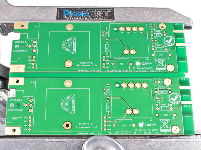
2.0 |
And we begin with a blank canvas.
|
 |

Click to enlarge
|
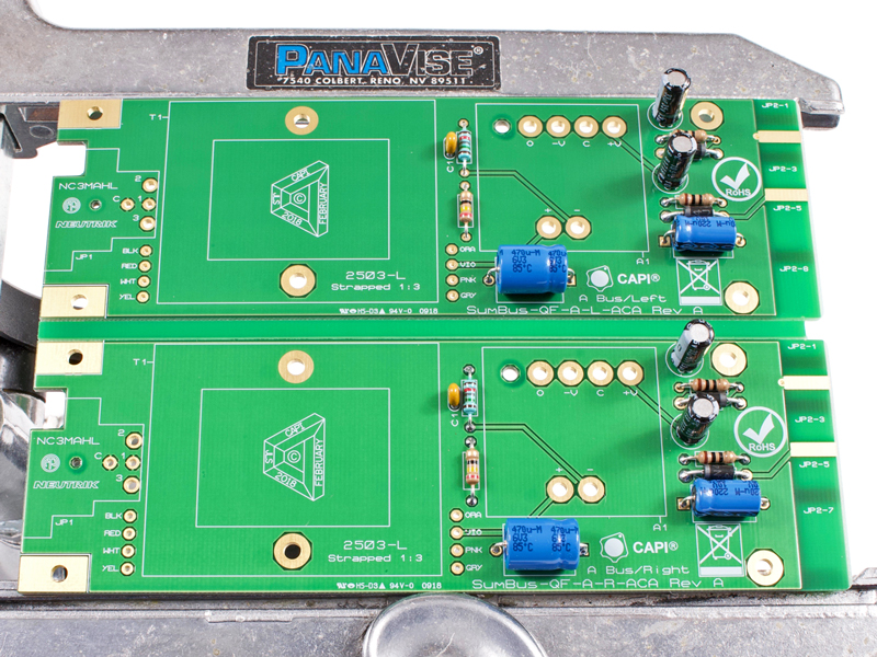
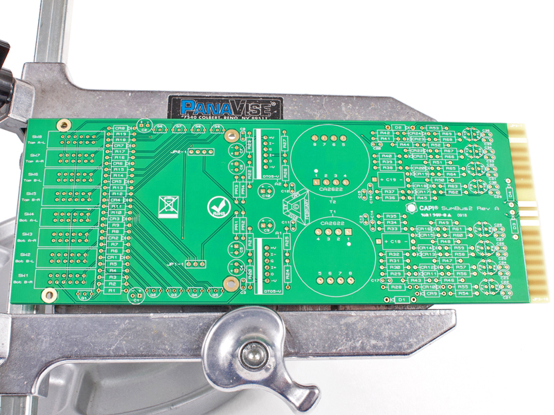
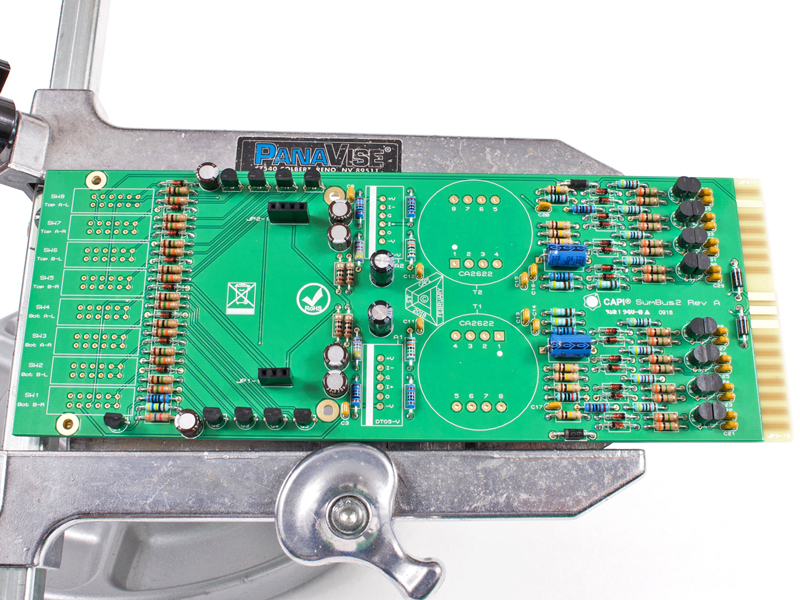
2.1 |
Install all resistors, diodes and capacitors following the proper BOM.
|
|
Click to enlarge
|
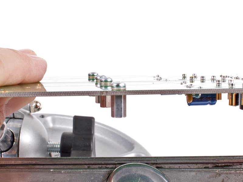
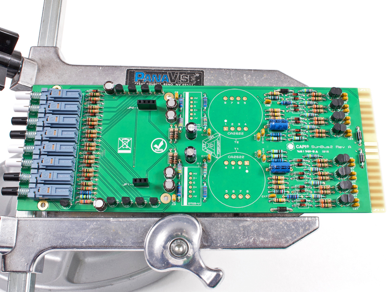
2.2 |
Install the Mill-Max opamp sockets. For this build they are inserted from the top of the PCB.
|
|

Click to enlarge
|
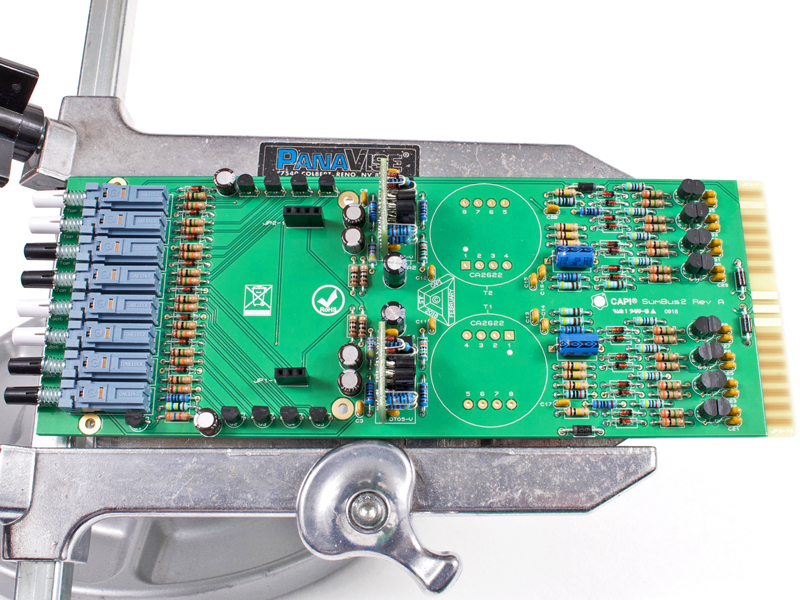
2.3 |
Secure the 5/16" standoffs to the PCB for the output transformers. Use a 3/16" pan head screw and a
#4 lockwasher for each standoff.
|
|

|
2.4 |
Break the two ACA PCBs apart as shown in section 4.4 below.
|
|
Click to enlarge
|
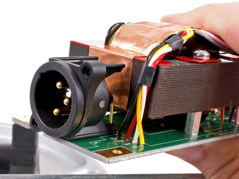
2.5 |
Secure the 2503 style outputs to the 5/16" standoffs. Use a 7/8" pan head screw and a #4 lockwasher
for each standoff.
|
|
Click to enlarge
|
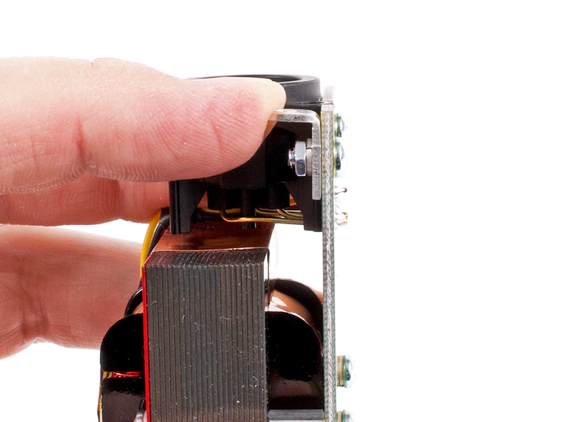
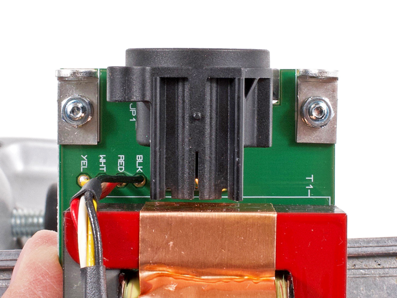
2.6 |
Trim, strip, tin and solder the 2503 leads to the PCB. Heat shrink tubing is not supplied. You can use some if you want
but its not required. The color designation labels are for the 2503-Litz outputs. If you have chosen the EA2503, follow
the cross reference chart on the EA2503's datasheet.
|
|
|
2.7 |
Install the discrete opamps. Use the tips shown on this page.
|
|

Click to enlarge
|
2.8 |
Install the Neutrik XLR connectors making sure they are all the way down tight to the PCB.
|
|
Click to enlarge
|
2.9 |
Secure the Keystone #616 brackets to the PCBs. Use a 1/4" pan head screw, mini-pattern hex nut and a #4
lockwasher for each bracket. Push the brackets all the way downward away from the PCB's rear edge.
|
|
Click to enlarge
|
2.10 |
Fully tighten making sure the brackets are properly aligned and not all crooked.
|
|

Click to enlarge
|
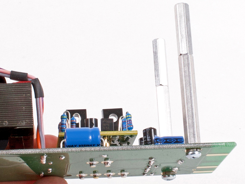
2.11 |
Snugly finger tight the 3/4" female/female standoffs onto the the 1-1/4" male/female standoffs.
Secure to the LEFT ACA PCB card using a 3/16" pan head screw and a #4 lockwasher.
|
|
Click to enlarge
|
2.12 |
Prepare the rear output panel by attaching two knurled thumb screws with #6 KEPS nuts. Those parts are found in the
Carcass Hardware Bag. If you are building a SumBus with only two ACA outputs, insert the plastic plugs into the B-Bus XLR
holes.
|
|
Click to enlarge
|
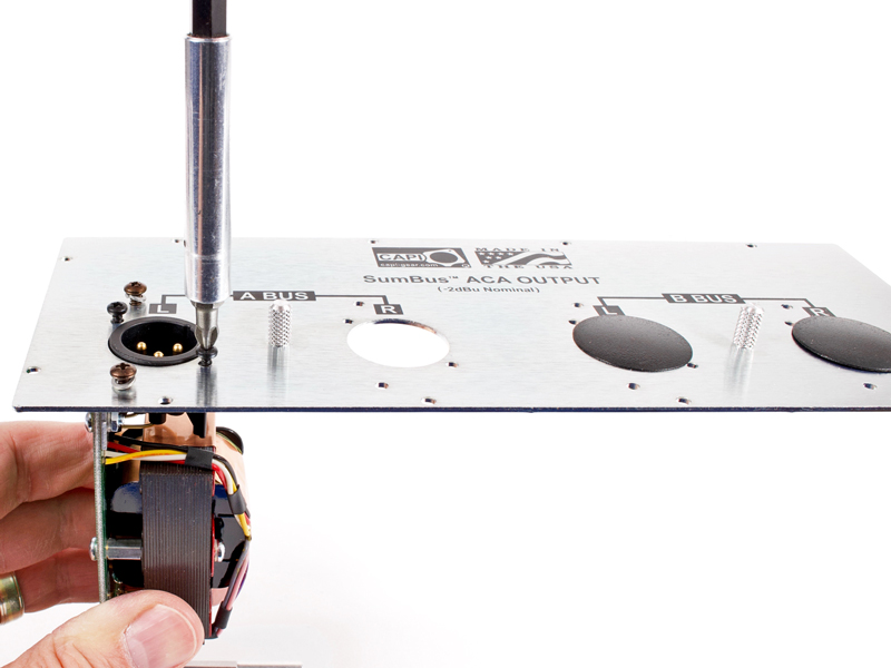
2.13 |
Start the 5/16" black pan head screws into the Keystone brackets and start the hi/low thread forming screws
into the Neutriks of the A-Bus Left card. Once all are started, fully tighten them.
|
|
Click to enlarge
|
2.14 |
Secure the A-Bus Right card to the rear panel in the same fashion.
|
|
Click to enlarge
|
2.15 |
Secure the A-Bus Right card to the 2" standoffs using a 3/16" pan head screw and a #4 lockwasher for each
standoff.
|
|
|
2.16 |
If you are building a 4 output SumBus, install the B-Bus cards in the same manor as we did the A-Bus cards.
Set the rear panel output assembly off to the side for now.
|
Click to enlarge
|
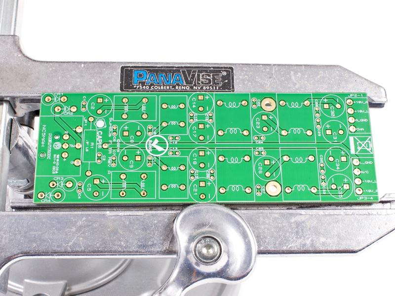
3.0 |
And we begin with a blank canvas.
|
|
Click to enlarge
|
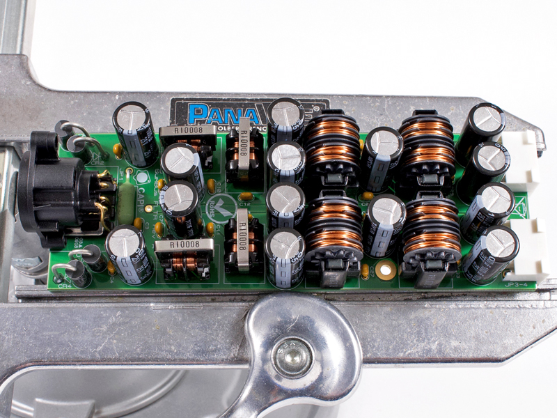
3.1 |
Using the BOM...
1. Install small ceramic caps.
2. Install resistor.
3. Install Molex headers. Keep them pushed back onto board edge.
4. Install diodes with cathode bands up.
5. Install small chokes.
6. Install large chokes.
7. Install electrolytic capacitors.
8. Install 5-pin Neutrik connector.
Set the DC Inlet PCB assembly off to the side for now.
|

Click to enlarge
|
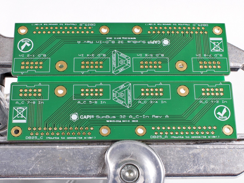
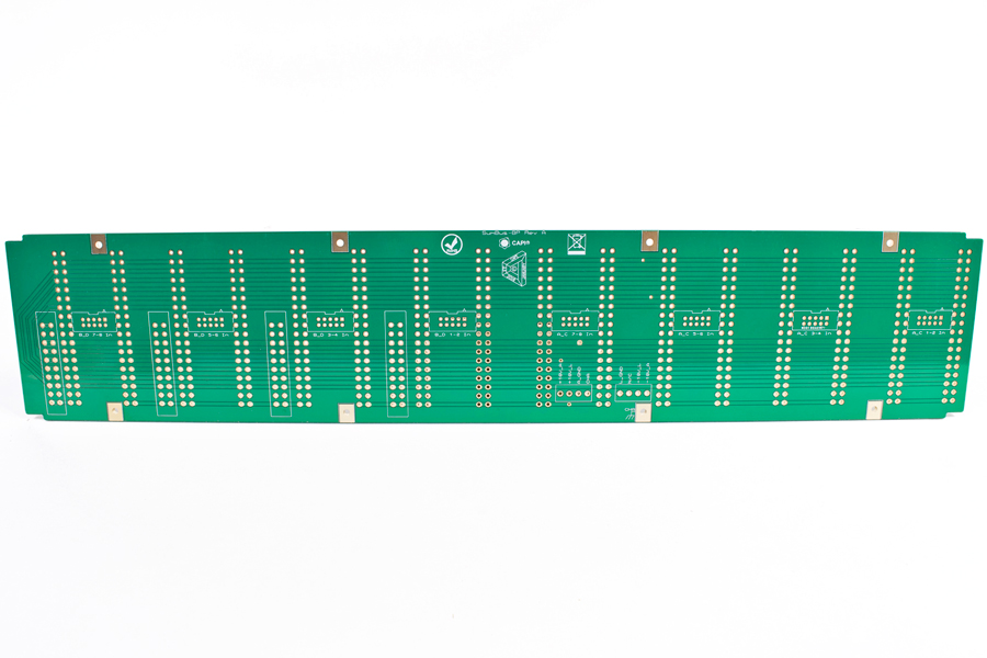
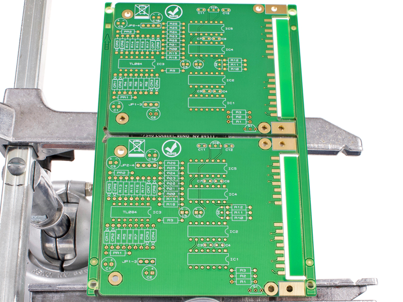
4.0 |
And we begin with a blank canvas.
|
|
Click to enlarge
|
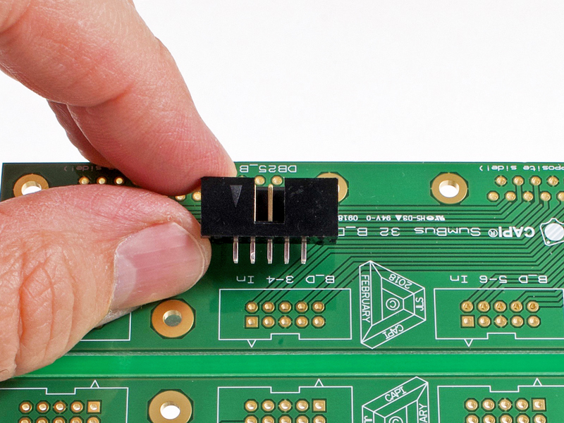
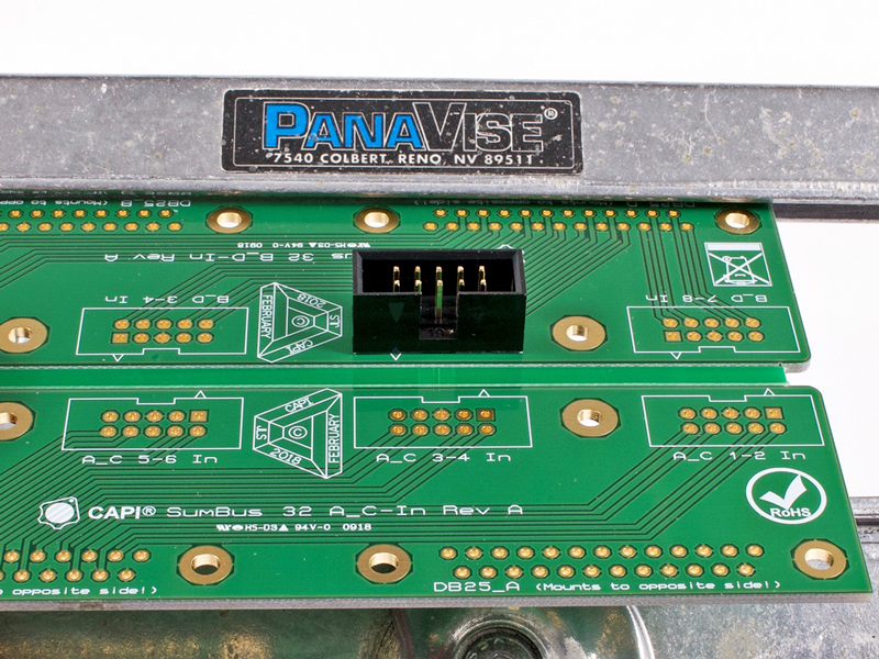
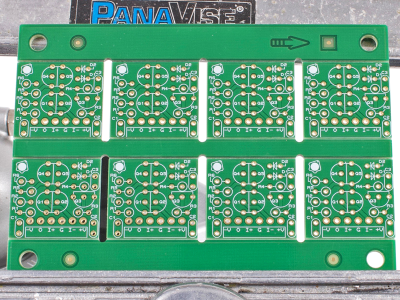
4.1 |
Pay close attention to the arrow indicating pin #1 on the IDC headers. This arrow is on the same side as the polarizer
notch. These MUST be orientated properly on the PCB.
|
|
Click to enlarge
|
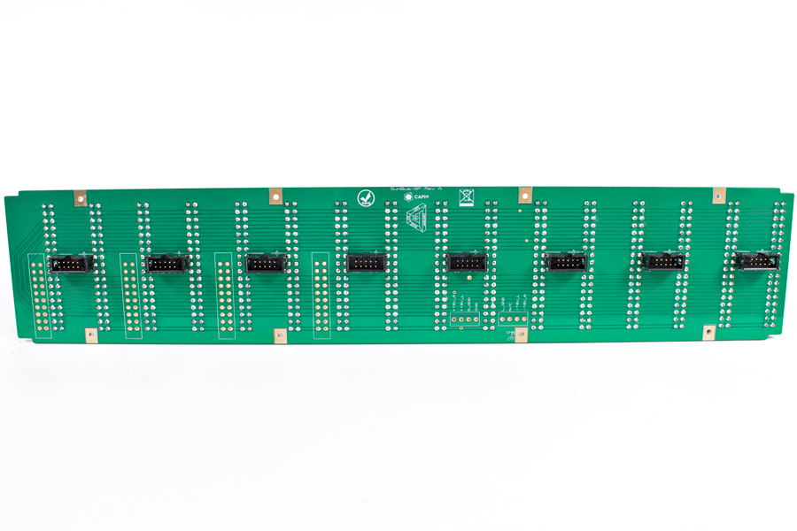
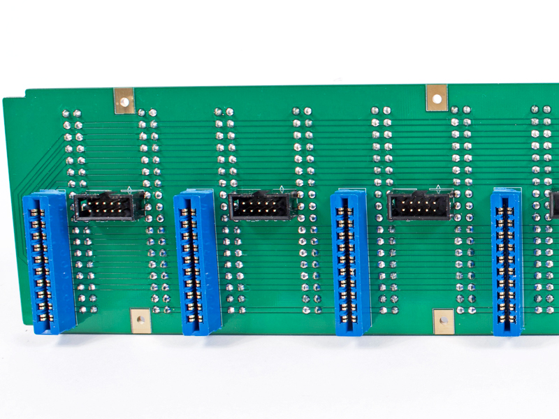
4.2 |
Install all IDC headers aligned as shown.
|
|
Click to enlarge
|
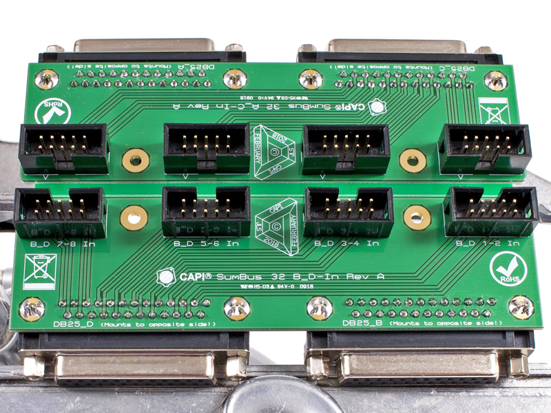
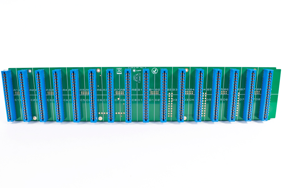
4.3 |
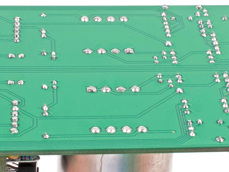
Install DB25 connectors. Pay special attention as they mount to the opposite side of the IDC headers. Solder their
mounting pins as well.
|
|

Click to enlarge
|
4.4a |
Break apart PCBs at the v-score.
|
Click to enlarge
|
4.4b |
Use needle nose pliers to remove waste.
|
|
Click to enlarge
|
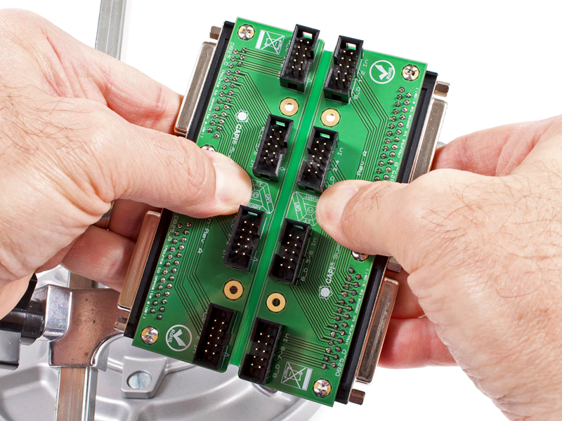
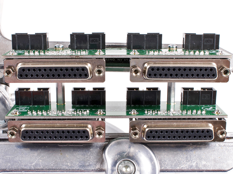
4.5 |
Final assemble the two PCBs. The A_C board is on the top and the B_D board is on the bottom. Use a 3/16" pan head
screw and #4 lockwasher thru each PCB into the 1-1/4" standoffs.
|
|
|
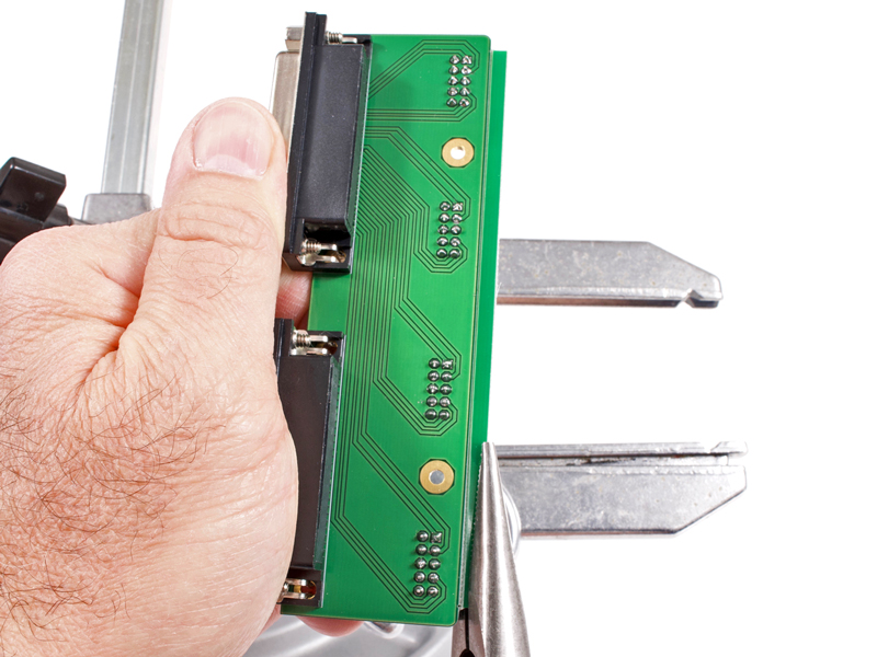
4.6 |
Set the DB25 input assembly off to the side for now.
|
|
5.0 |
Using a regular pair of scissors, cut the 10-wire ribbon cable into the following lengths:
A_C 1-2 = 6" (152mm)
A_C 3-4 = 6" (152mm)
A_C 5-6 = 6.25" (159mm)
A_C 7-8 = 6.5" (165mm)
B_D 1-2 = 11.75" (298mm)
B_D 3-4 = 12.375" (314mm)
B_D 5-6 = 13" (330mm)
B_D 7-8 = 13.625" (346mm)
|
|
Click to enlarge
|
5.1 |
With the red stripe (wire #1) facing towards you, slide an IDC header on with the polarizer key facing outward
and the small arrow aligned towards the red wire.
|
|

Click to enlarge
|
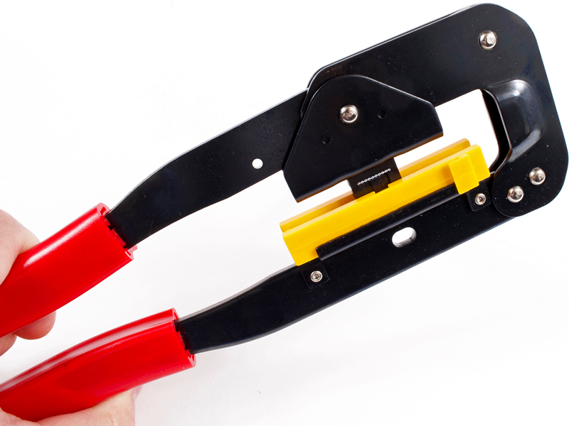
5.2a |
Adjust so the ribbon cable is flush with the edge of the connector and crimp using the
IDC Ribbon Crimping Tool.
|
Click to enlarge
|
5.2b |
The polarizer key will fit inside of the yellow insert of the crimper.
|
|
Click to enlarge
|
5.3 |
Flip the assembly over with the red stripe (wire #1) still facing towards you. Slide a 2nd IDC header on with
the polarizer key facing outward and the small arrow aligned towards the red wire, then crimp.
|
|
Click to enlarge
|
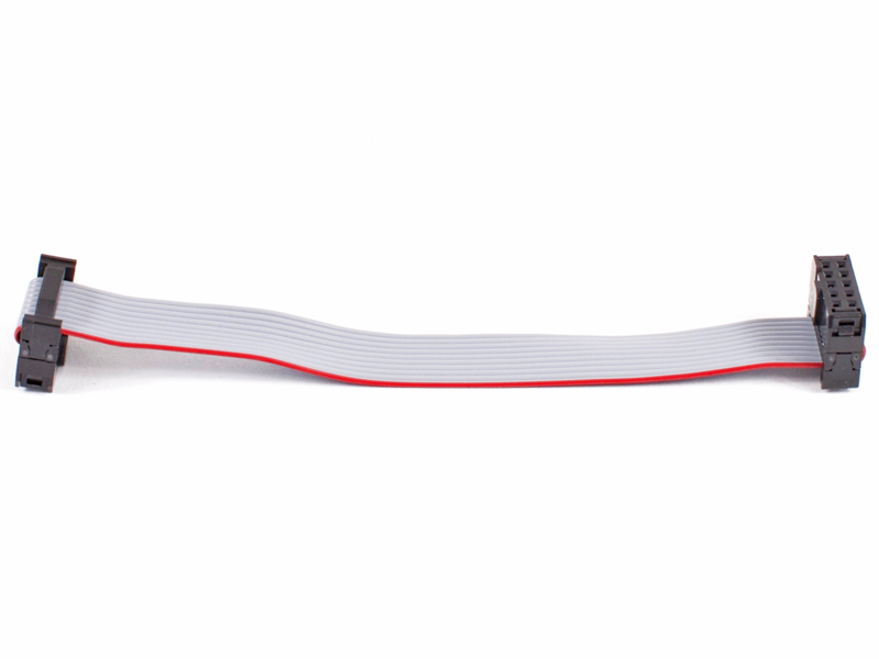
5.4 |
This is where we are so far.
|
|

Click to enlarge
|
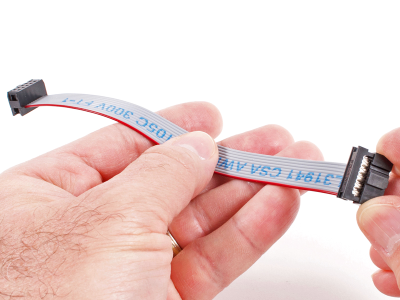
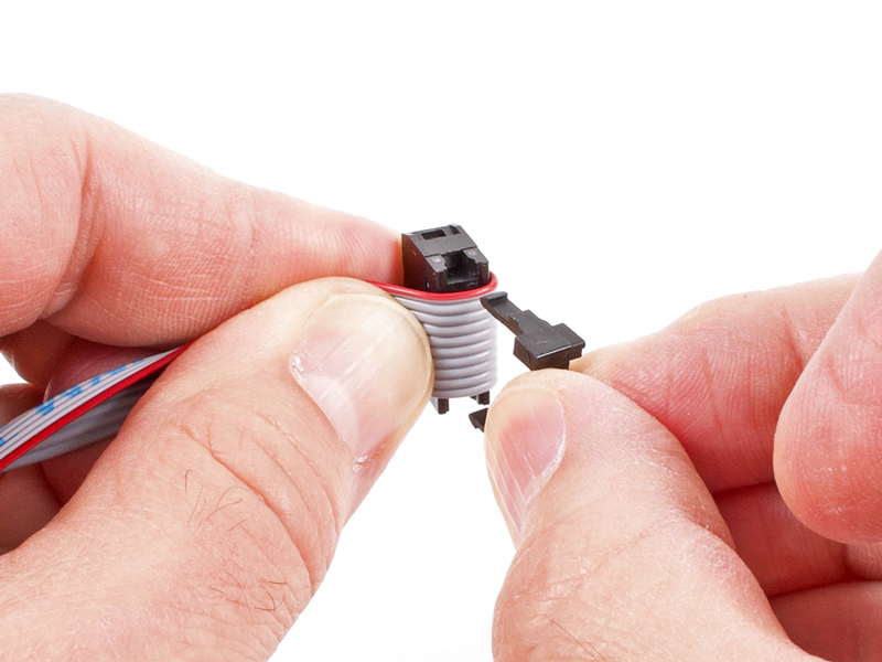
5.5 |
Fold the ribbon cable over one of the connectors and snap a stain relief into place. Do this on both ends.
|
|
Click to enlarge
|
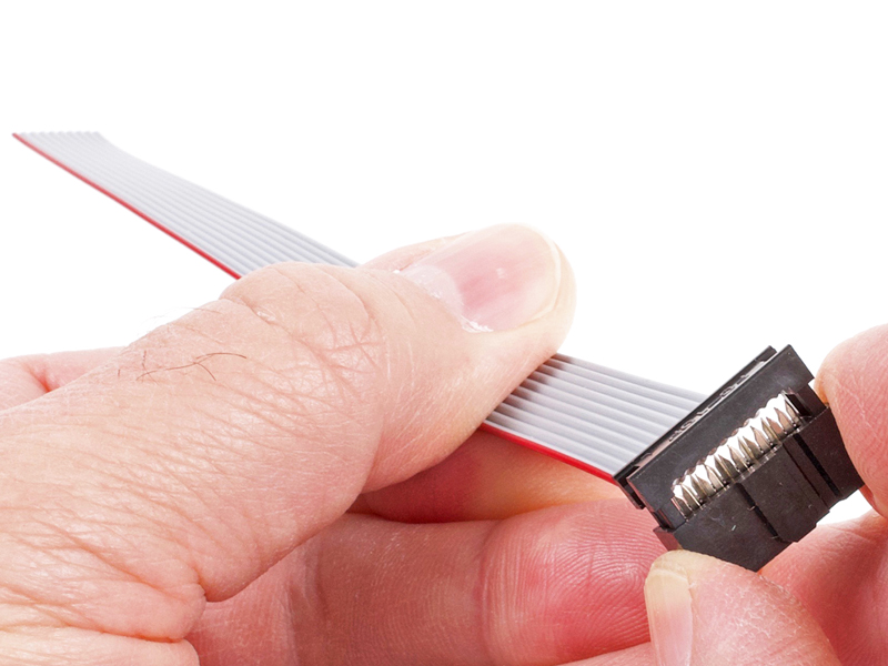
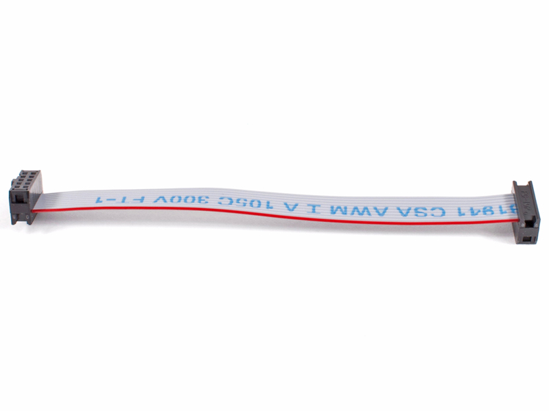
5.6 |
A completed cable will have both polarizer keys facing inward towards each other.
|
|
|
5.7 |
Rinse and repeat for the remaining 7 cables.
|

Click to enlarge
|
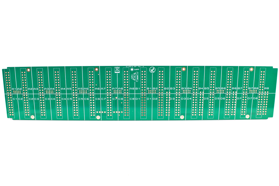
6.0a |
And we begin with a frontal blank canvas.
|
Click to enlarge
|
6.0b |
And the rear blank canvas.
|
|
Click to enlarge
|
6.1 |
Install all sixteen 36-pin card edge connectors.
As a tip to make final assembly easier, take an unpopulated channel card and insert it into each of the sixteen card edge
connectors. They are fairly stiff when virgin and this will open them up slightly.
|
|
Click to enlarge
|
6.2 |
Install the eight 10-pin IDC headers. Observe polarity as before.
|
|
Click to enlarge
|
6.3 |
Install the four 20-pin card edge connectors.
|
|
Click to enlarge
|
6.4 |
Install the two 4-pin .156" headers making sure they are perpendicular to the PCB.
|
|
Click to enlarge
|
6.5 |
Locate the Keystone #621 brackets from the Carcass Hardware Bag. The first step is to determine the difference
between the longer .375" side and the shorter .343" side of the brackets. The shorter side goes against the
backplane PCB. To help recognize, the shorter side has tooling marks in the face from the manufacturing process.
|
|
Click to enlarge
|
6.6 |
Install all eight of the Keystone #621 brackets to the rear of the backplane PCB using 5/16" black pan head
screws and #4 lockwashers. Remember, the shorter side of the Keystone brackets are against the PCB.
|
|
Click to enlarge
|
6.7 |
Make sure all brackets are properly aligned with the exposed flat edges being parallel to the edge of the PCB.
|
|
|
6.8 |
Set the backplane assembly off to the side for now.
|
Click to enlarge
|
7.1 |
Secure the two sides to one of the top/bottom panels with eight 1/4" black flat head screws. The
top/bottom panels are interchangeable but are not reversible. The front has the three rows of vent holes.
|
|
Click to enlarge
|
7.2 |
Secure the backplane assembly to the bottom panel with four 1/4" black flat head screws.
|
|

Click to enlarge
|
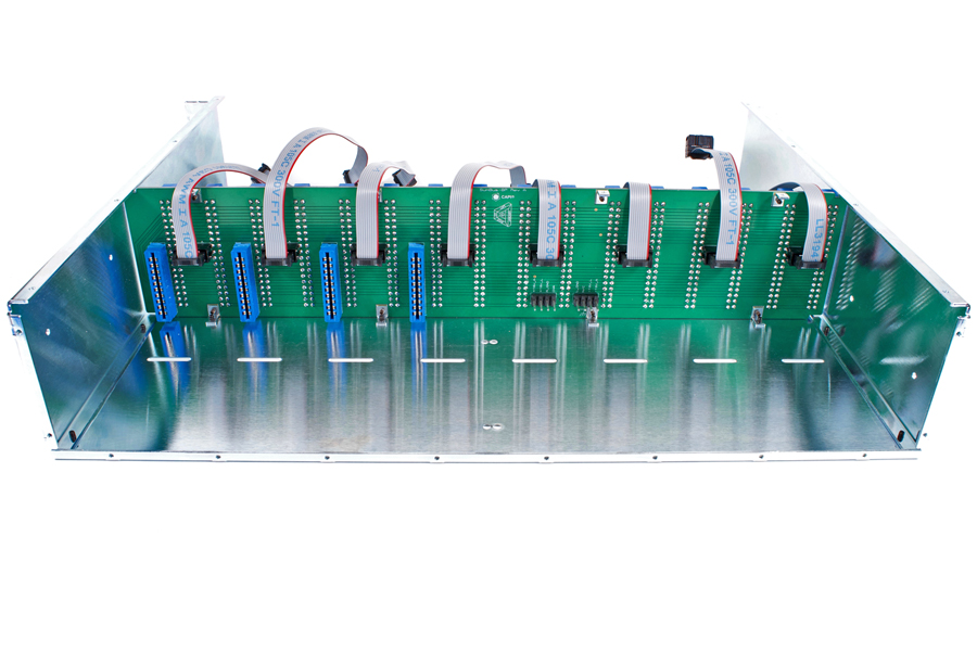
7.3 |
Plug all eight of the ribbon cable assemblies into their respective headers and flip over the backplane towards the front.
All of the red wires should be facing channel #1 if things were done right.
|
|
Click to enlarge
|
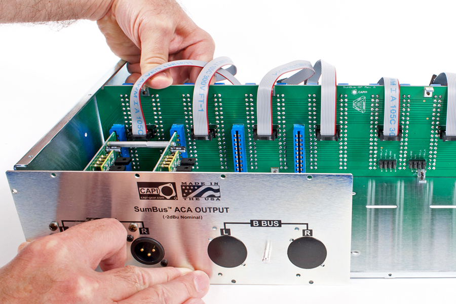
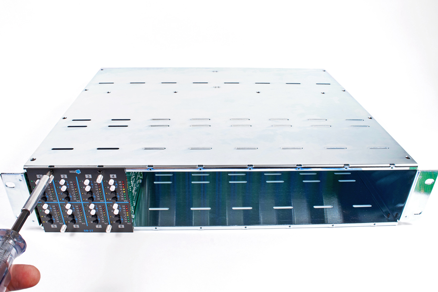
7.4 |
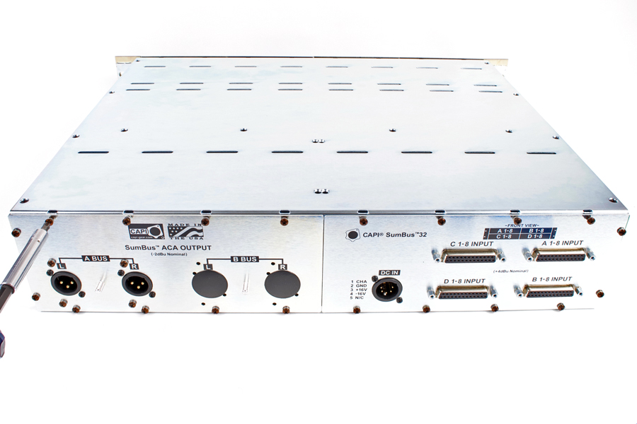
Plug the rear ACA output panel assembly into the backplane. MAKE SURE you support the backplane from the front so
you don't break anything!
|
|
Click to enlarge
|
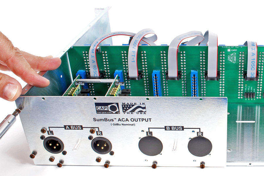
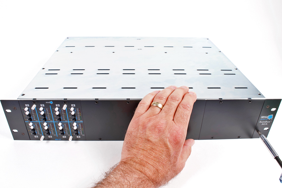
7.5 |
Start all six of the rear output panel perimeter 5/16" black pan head screws and lockwashers before fully
tightening them all.
|
|
Click to enlarge
|
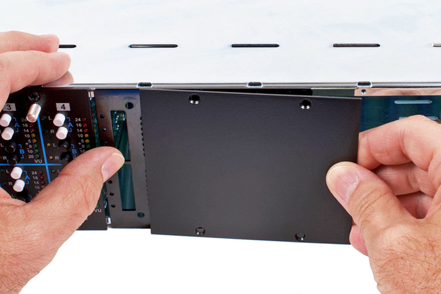
7.6 |
Maneuver the internal shield into position.
|
|
Click to enlarge
|
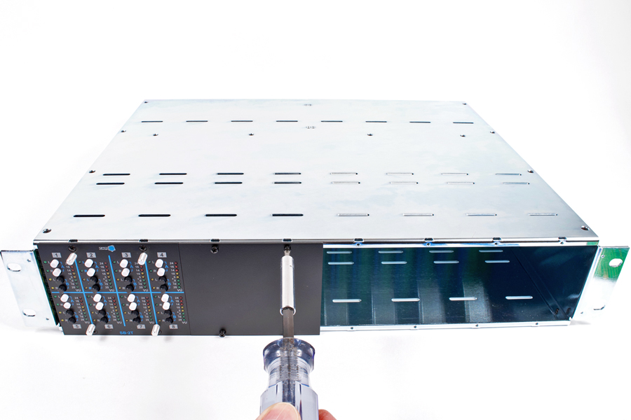
7.7 |
Secure the shield thru the side panel with two 5/16" black pan head screws. Use a #4 lockwasher and small
pattern hex nut on the inside. Secure the shield thru the bottom panel with two 1/4" black flat head screws. Use a
#4 lockwasher and small pattern hex nut on the inside.
|
|
Click to enlarge
|
7.8 |
Fully insert the DC Inlet Filter PCB into position onto the .156" Molex headers.
|
|
Click to enlarge
|
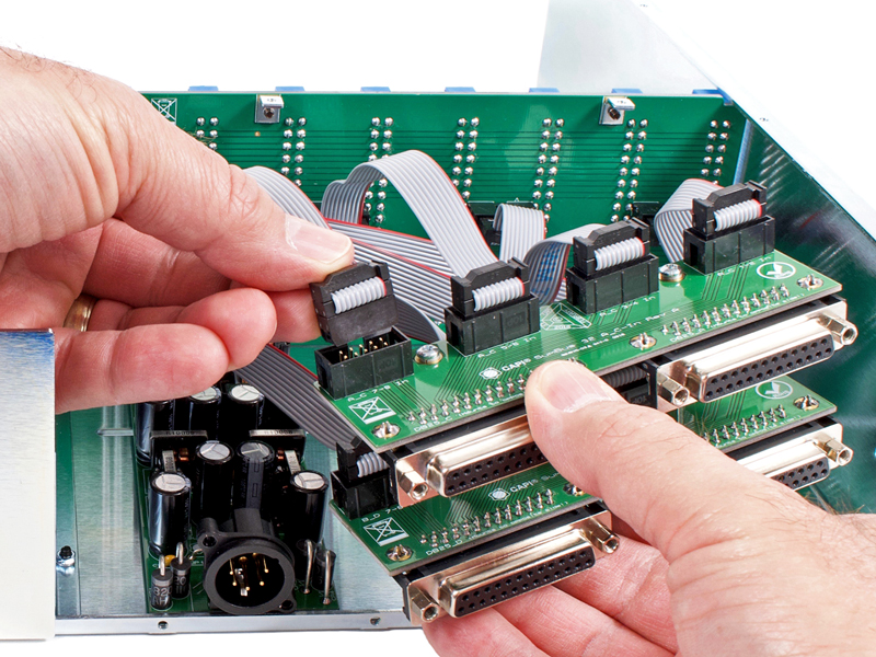
7.9 |
Insert ribbon cables 5-8 into their respective headers on the lower B_D DB25 PCB.
|
|
Click to enlarge
|
7.10 |
Insert ribbon cables 1-4 into their respective headers on the upper A_C DB25 PCB.
|
|

Click to enlarge
|
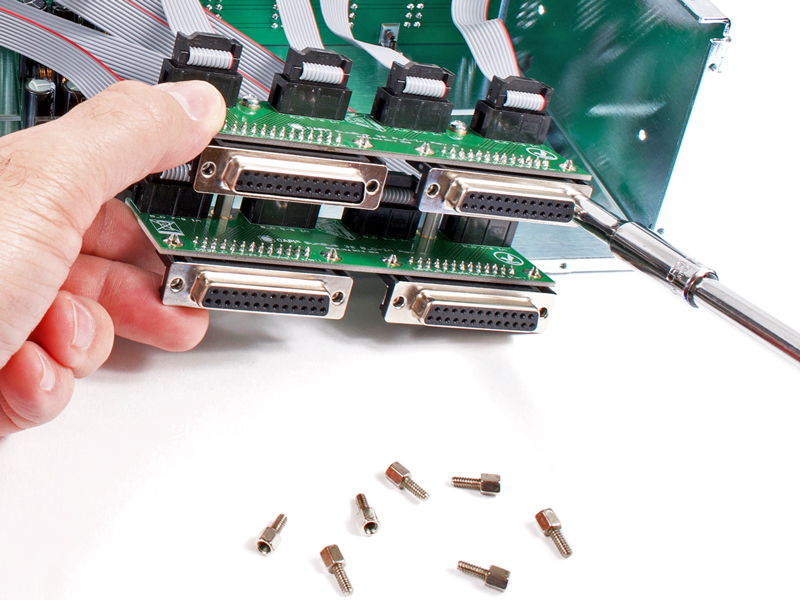
7.11 |
Remove and discard the factory jackscrews that come on the DB25s.
|
|
Click to enlarge
|
7.12 |
Start all eight supplied jackscrews with a #4 lockwasher thru the rear input panel and into the DB25 connectors. Get
all of them threaded about 1/2 way in before starting to tighten. They should be nice and snug but DO NOT
over-tighten or you will sheer them off and have a real mess on your hands!
|
|
Click to enlarge
|
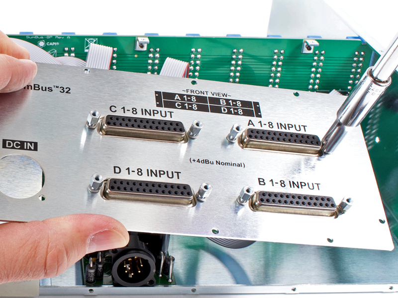
7.13 |
Slip rear input panel over DC Inlet Neutrik and secure with two hi/low thread forming screws.
|
|

Click to enlarge
|
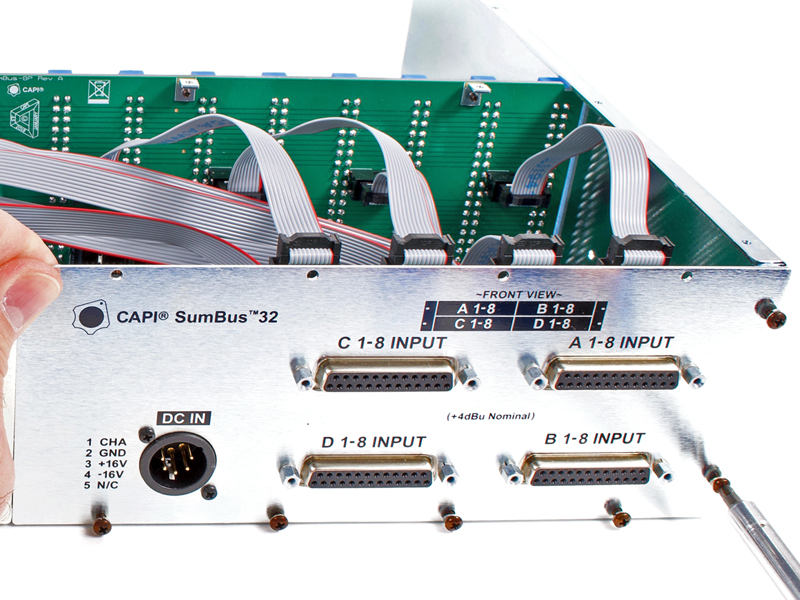
7.14 |
Start all six of the rear input panel perimeter 5/16" black pan head screws and lockwashers before fully
tightening them all.
|
Click to enlarge
|
8.0 |
And we begin with a blank canvas.
|
|
Click to enlarge
|
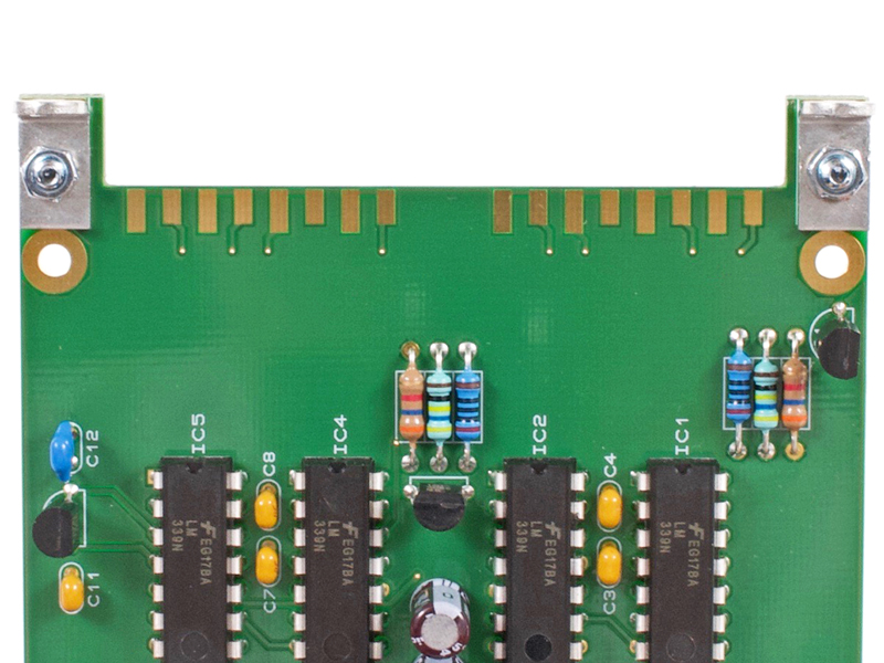
8.1 |
Install all diodes, resistors, and small ceramic capacitors following the proper BOM.
A 1/4W Lead Forming Tool is highly
recommended for neat and tidy looking work.
|
|
Click to enlarge
|
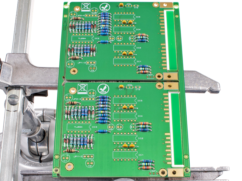
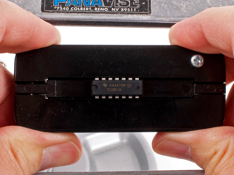
8.2 |
Use an IC Pin Straightener to
properly form the leads of the LM339s and the TL084s. Solder the ICs into place.
Install all remaining board level components. DO NOT install LEDs at this time.
Break the 2 PCBs apart at the v-score as we did with the DB25 and ACA boards.
|
|
Click to enlarge
|
8.3 |
Secure the Keystone #616 brackets to the PCBs. Use a 1/4" pan head screw, mini-pattern hex nut and a #4
lockwasher for each bracket. Push the brackets all the way downward away from the PCB's front edge as we did for the
ACAs in step 2.9 above.
|
|

Click to enlarge
|
8.4 |
Fully tighten making sure the brackets are properly aligned and not all crooked.
|
|
|
8.5 |
Set the meter PCB assembly off to the side for now.
|
Click to enlarge
|
9.0a |
The first task is to build the DTO5 opamps. They are v-scored in a sheet of 8 to make life easier.
Please visit the DTO5 build page and then return here.
|
|
Click to enlarge
|
9.0b |
And now we begin with a blank canvas.
|
|
Click to enlarge
|
9.1 |
Using the BOM...
1. Install small package diodes.
2. Install resistors.
3. Install large package diodes.
4. Install small ceramic caps.
5. Install transistors.
6. Install electrolytic capacitors.
7. Install .1" receptacles.
|
|
Click to enlarge
|
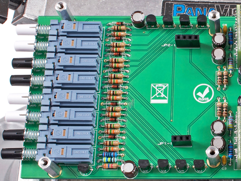
9.2 |
Install Toneluck pushbutton switches and switch caps.
|
|
Click to enlarge
|
9.3 |
Install DTO5 opamps.
|
|
Click to enlarge
|
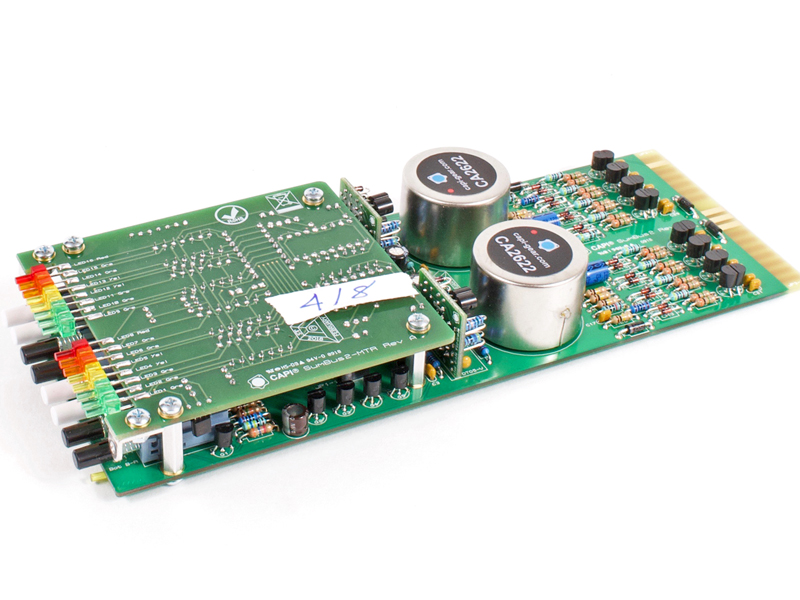
9.4a |
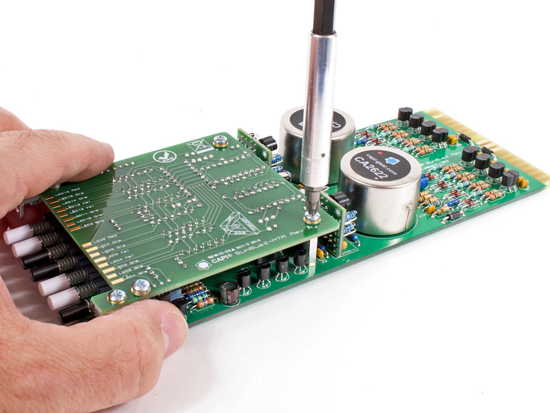
Install the CA2622 input transformers.
|
Click to enlarge
|
9.4b |
Try and maintain a maximum 0.03" space between the bottom of the can and the PCB. DO NOT exceed this offset
height or you will have issues with the transformer can shorting out to the adjacent PCB.
|
Click to enlarge
|
9.4c |
Trim all leads for the 2622s. This is mandatory or they will short out against the adjacent transformer.
|
|
Click to enlarge
|
9.5 |
Secure the four 5/8" standoffs to the PCB. Use a 3/16" pan head screw and a #4 lockwasher for each
standoff.
|
|

Click to enlarge
|
9.6 |
Plug meter PCB into channel PCB and secure with a 3/16" pan head screw and a #4 lockwasher for each standoff.
|
Click to enlarge
|
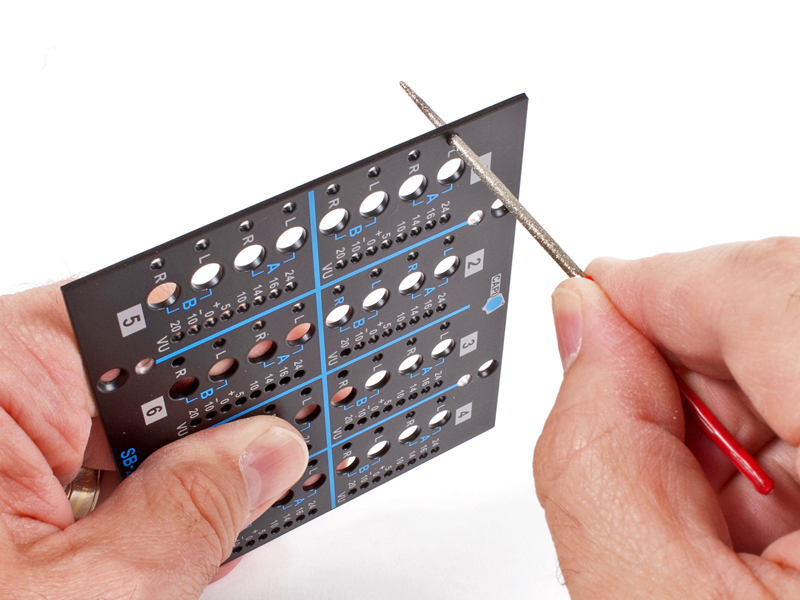
10.1 |
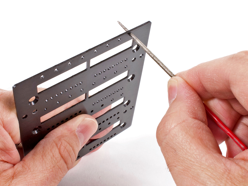
Prepare and clean the LED holes on the sub-front panel with the provided 2mm needle file. These plates are black zinc
plated steel. Some holes have a little slag build up that will make LED install a bear. **CAUTION, eye protection is
recommended!
|
|
Click to enlarge
|
10.2 |
Prepare and clean the LED holes on the front panel skin with the provided 2mm needle file. These plates are wet painted
aluminum. Some holes have a little extra paint build up that will make LED install a bear. I recommend clearing each and
every one. **CAUTION, eye protection is recommended!
|
|
Click to enlarge
|
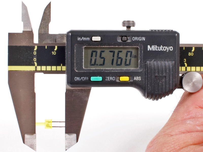
10.3a |
Before trimming the leads, take note as to the difference between cathode and anode on the inside of the LEDs. You will
need to distinguish which is which after cutting the leads. Cut all LEDs to a 9/16" overall length.
|
Click to enlarge
|
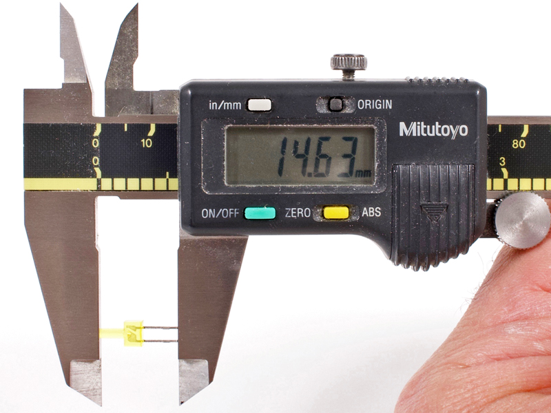
10.3b |
That is appx 14.6mm for anyone not in the USA.
|
Click to enlarge
|
10.3c |
Make some marks on a piece of paper or use something as a jig.
|
|

Click to enlarge
|
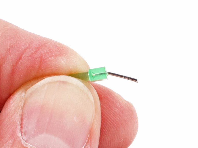
10.4 |
Slightly over-bend the yellow and green LEDs used for pushbutton switch indication.
|
|
Click to enlarge
|
10.5 |
Lay the the indication LEDs on a flat hard surface and push them downward until flat. This will align the tips of the
leads with the LED body.
|
|
Click to enlarge
|
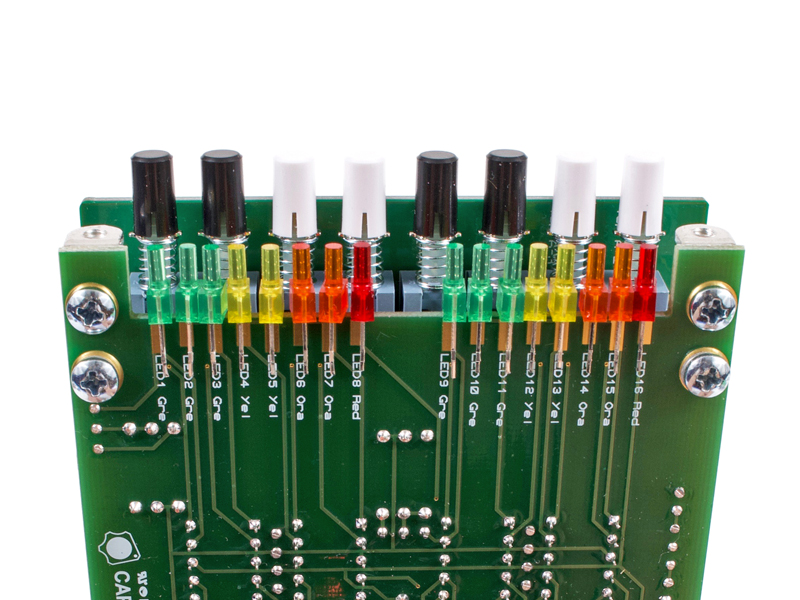
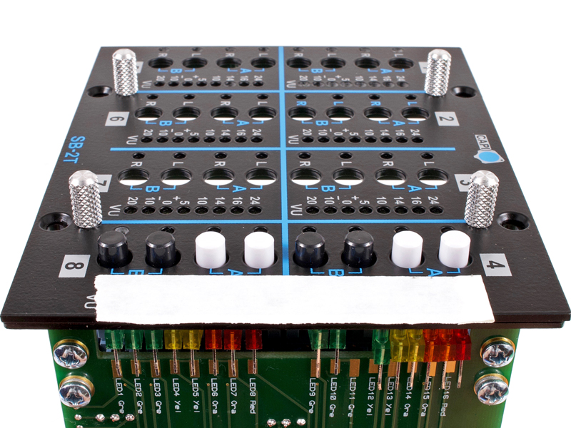
10.6 |
Observing polarity, straddle all of the meter LEDs over the edge of the meter PCB in proper order. I always double check
polarity with a magnifier before continuing. Remember, the anode (longer lead) goes to the long pads and the cathode (shorter lead)
goes to the short pads.
|
|

Click to enlarge
|
10.7 |
Secure the PCB assembly to the sub-front panel with two 3/16" flat head screws.
|
|
Click to enlarge
|
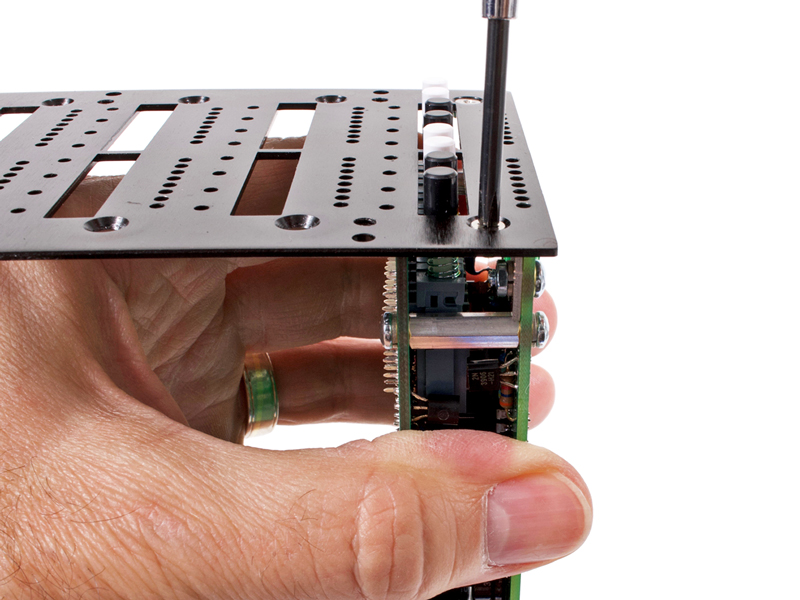
10.8 |
Install the screws nice and snug but not gorilla tight. You can see that this method will always insure the PCBs get
pulled tightly to the back of the sub-front panel.
|
|
Click to enlarge
|
10.9 |
Drop the front panel skin into place and start the four knurled thumb screws. Do not fully tighten them yet.
|
|
Click to enlarge
|
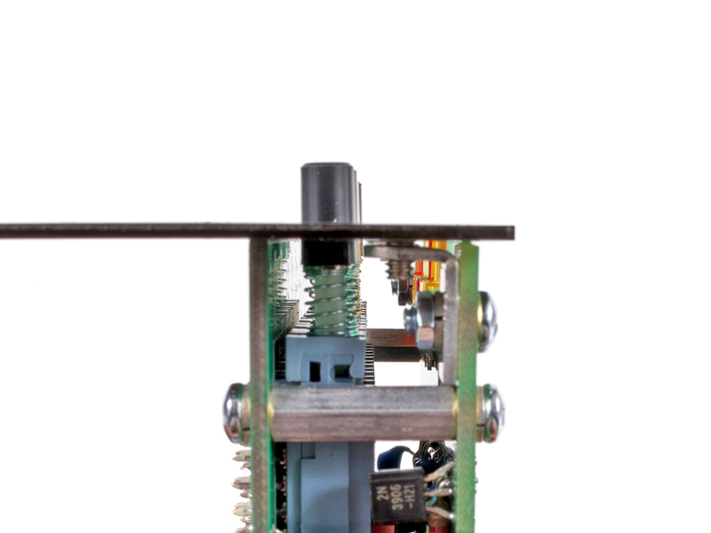
10.10 |
Insert four LEDs into four of the perimeter meter LED holes. Make sure they fall fully in and sit flat to the front panel
skin. Snug up the knurled screws.
|
|
Click to enlarge
|
10.11 |
Put a piece of console tape on the front panel skin over the particular meter LED holes.
|
|
Click to enlarge
|
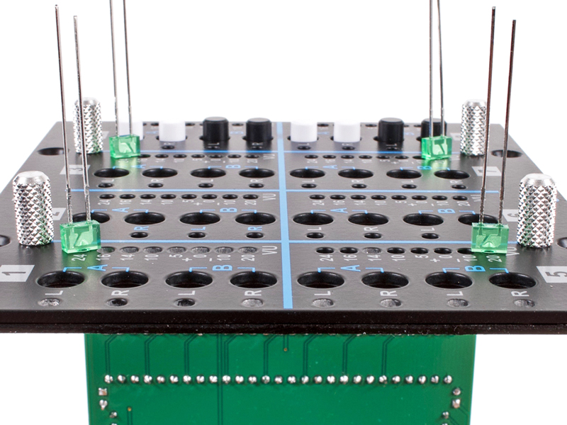
10.12 |
Slip all meter LEDs into their final positions. The console tape will hold them in place as well as keep them nice and
flush to the front panel skin.
|
|

Click to enlarge
|
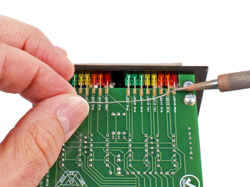
10.13 |
Solder the exposed LED leads.
|
|
Click to enlarge
|
10.14 |
Loosen the knurled thumb screws. Move the four upside down LEDs into perimeter indication holes and retighten the knurled
thumb screws.
|
|
Click to enlarge
|
10.15 |
Apply console tape over the required indication holes. Insert the LEDs and solder all of their leads.
|
|
Click to enlarge
|
10.16 |
Take the entire assembly apart. Unscrew the meter PCB from channel PCB. Inspect the inside of the PCB LED leads to make
sure none are too long and hanging off of a pad into the ground plane area. Solder the remaining meter LED leads.
|
|

Click to enlarge
|
10.17 |
Put the channel/meter assembly back together. I recommend labelling them so they go back into the same spot as was
used for LED installation. It may make final front panel skin installation easier.
|
|
|
10.18 |
Repeat the above section 10 steps as required for your channel count. I suggest using the final spot for the channel as
the location to use for LED installation. This includes sub-front panels and skins.
|
Click to enlarge
|
11.1 |
Slowly and carefully insert the 8 channel blocks into their card edge connectors. It may take some finessing. Do not push
on the LEDs. Make sure you support the top of the backplane so nothing gets broken.
|
|
Click to enlarge
|
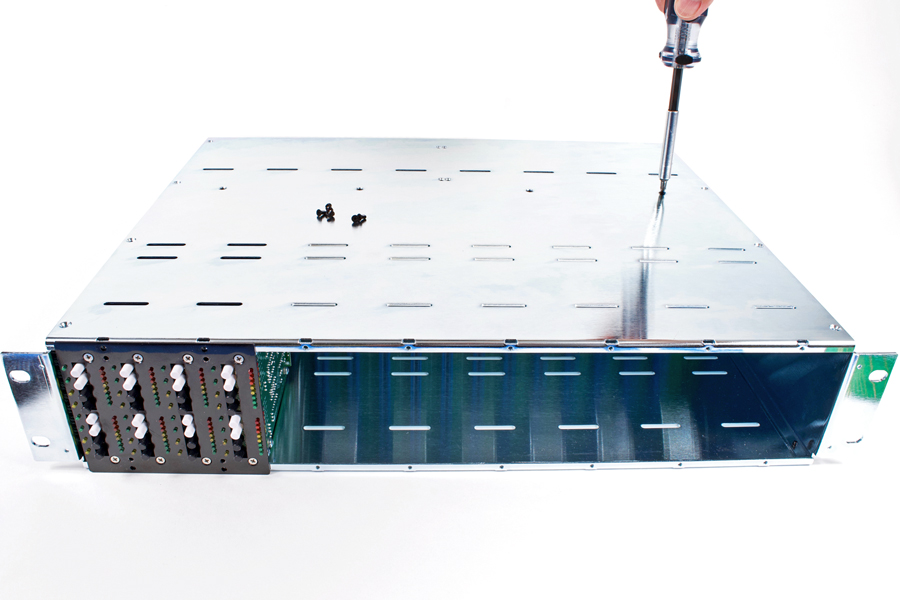
11.2 |
When all channels are inserted, put the top cover in place and screw home. Install all twelve of the 1/4" black
flat head screws starting with the 4 for the backplane first.
|
|
Click to enlarge
|
11.3 |
Install front panel skins as required. Carefully slip over the LEDs. Next install the knurled thumb screws and finish up
with the oval head module screws.
|
|
Click to enlarge
|
11.4a |
If blank front panel skins are being used, install with sub-front panels behind them.
|

Click to enlarge
|
11.4b |
Screw in place with oval head module screws.
|
|
Click to enlarge
|
11.5 |
Install rack ear cover plates using 1/8" black flat head screws. Do not over tighten or they will strip out.
|
|
Click to enlarge
|
11.6 |
Turn the entire unit around and install the eight 5/16" black pan head screws into the top with #4
lockwashers.
|
|
The contents of this assembly guide page, including but not limited to all text, photographs and diagrams, is the
intellectual property of Classic Audio Products, Inc. Reproduction or re-publication by any means whatsoever, whether
electronic, mechanical or electro-mechanical, is strictly prohibited under International Copyright laws. The sole purpose
for this document is to aid in the assembly of the SumBus kit offered by Classic Audio Products, Inc.
Commercial use is prohibited.
|
 |
|
Classic Audio Products, Inc. is a DIY parts / kit retailer and provides no direct support for any of the products
available on this site. Support for the kits can be found at the respective [Build] thread at groupdiy.com. Any support
Classic Audio Products, Inc. chooses to provide, is provided "as is" without warranty of any kind. We cannot offer
any guarantee as to the consequences of the support provided. Should the support cause damage or loss of any kind, Classic
Audio Products, Inc. shall not be held liable to you or any other person for indirect, special, punitive, incidental, or
consequential damages or losses. While the successful build rate is extremely high, there is no guaranteed favorable
outcome. Always research and plan any project you undertake thoroughly. Sometimes, a project is over your head, and it
just makes more sense to hire a qualified professional.
|
|
 |
| |
|
|
|
| 0 items |
|
|
|
 |
Curative Notice |
|
|
| Classic Audio Products, Inc. is not affiliated with API.
Customers and fans should not refer to Classic Audio Products, Inc. as "Classic API."
API is a registered trademark of Automated Processes Incorporated. Classic Audio Products, Inc. has no affiliation with
Automated Processes Incorporated. |
|
|
|
|
Bestsellers |
|
|
|
Manufacturers |
|
|
|
Quick Find |
|
|
|
|
|
|
|


 Preface