|
| HPA500 Rev A Pictorial Build Guide |
|
|
 |
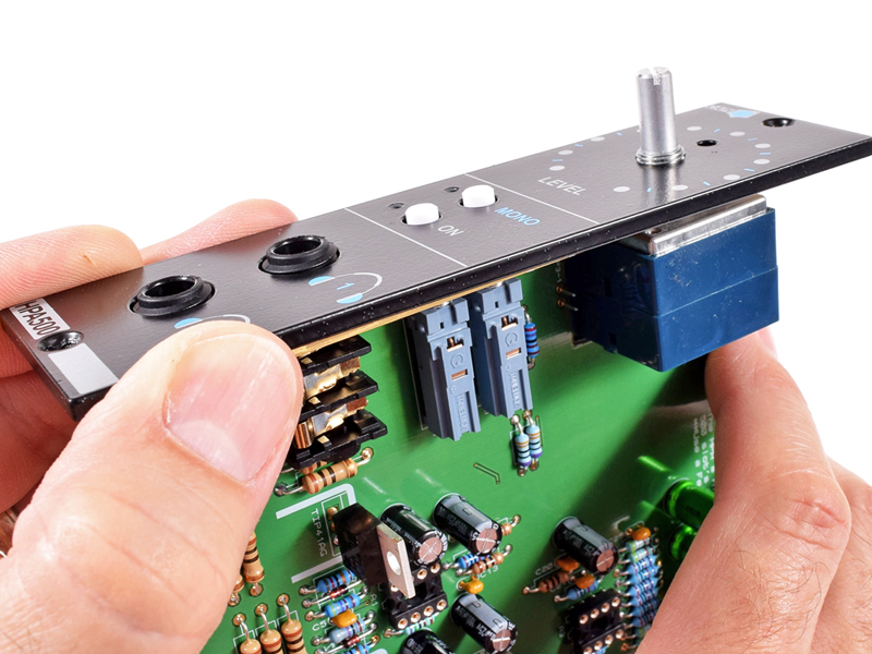
|
MAKE SURE the build guide you follow matches the Revision of the PCB you are building!
|
Click to download
|
2.A.1 |
Properly identifying and sorting the resistors is very important. This task can be done many ways. If you wanna
roll old school, click the pic to the left to download my Resistor Color Code Chart.
|

Click to enlarge
|
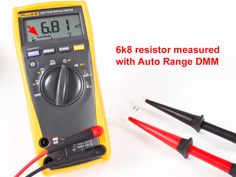
2.A.2 |
The best way is to use a high quality DMM (digital multimeter) that has an Auto Range function.
|
Click to enlarge
|
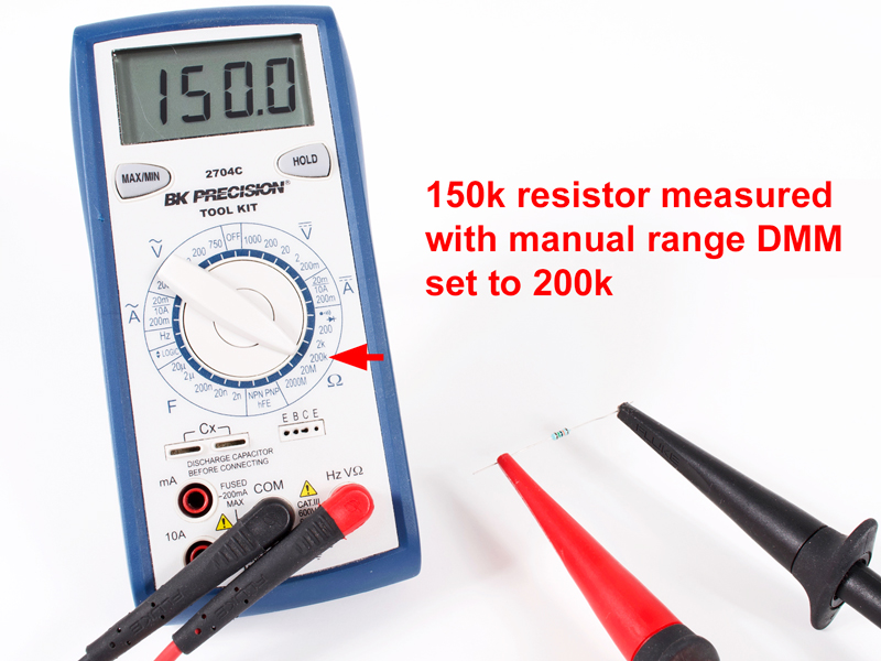
2.A.3 |
If your DMM has a Manual Range, make sure you have it set properly or you will get no reading or even a false reading.
|

Click to enlarge
|
2.A.4 |
Note the different range settings used to identify the high value resistor.
|

Click to enlarge
|
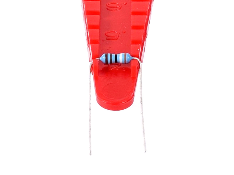
2.A.5 |
Once properly identified, all of the smaller resisters and all diodes can be bent to .4" centers. The
1W 10Rs are .6" centers and have a 1/2W body size. A handy dandy
Lead Forming Tool
can really make this easy and make your project look neat and tidy!
|
 |
Click to enlarge
|
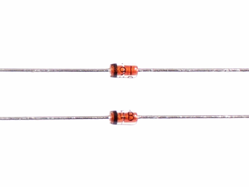
2.A.6 |
Fairchild 1N914 diode, label is "91 4B"
|
|
Click to enlarge
|
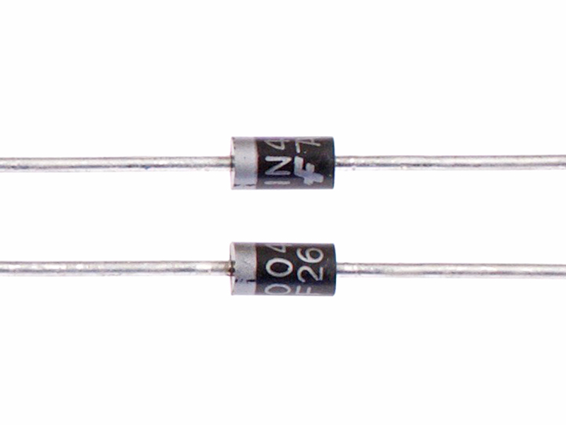
2.A.7 |
Fairchild 1N4004 diode, label is "1N4004"
|
Click to enlarge
|
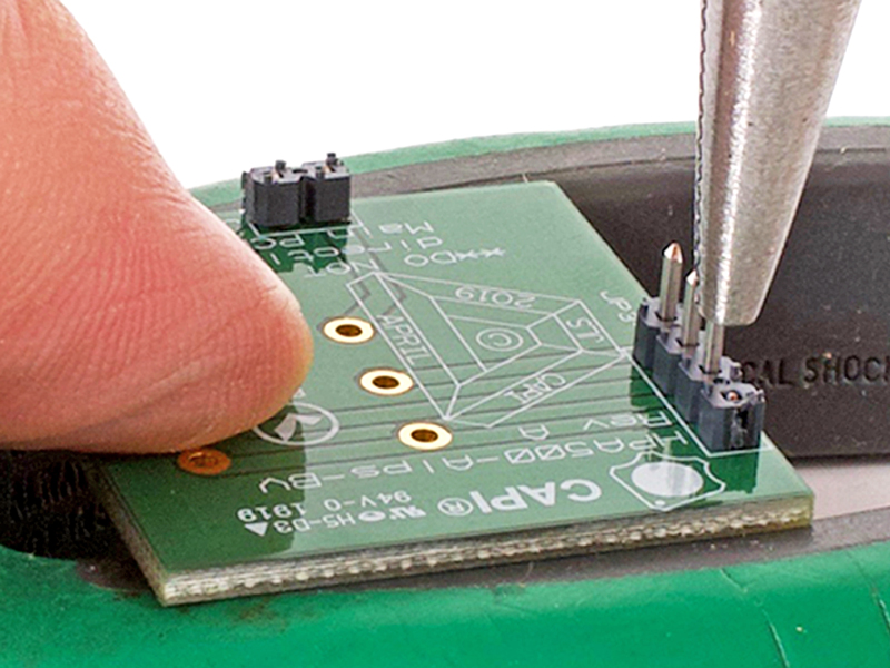
3.1 |
Insert the headers thru the Alps-BV PCB from the bottom. Support the PCB in a way that you can use a needle nose pliers or
similar to push each pin down tight to the black plastic shroud. The edge of your bench or table will work fine.
|
|

Click to enlarge
|
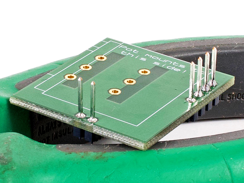
3.2 |
Neatly solder the header pins from the top of the PCB making sure the shroud is down tight and the pins are perpendicular
to the PCB.
|
|
Click to enlarge
|
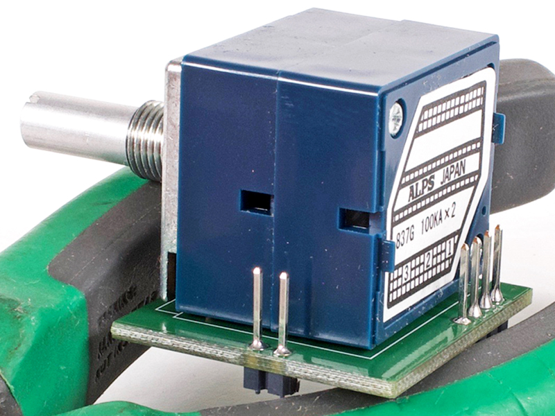
3.3 |
Install the Alps Blue Velvet pot tight to the top of the PCB. I alternate soldering the pins to not heat up the inside of
the pot too much. Set this subassembly off to the side until later.
|
Click to enlarge
|
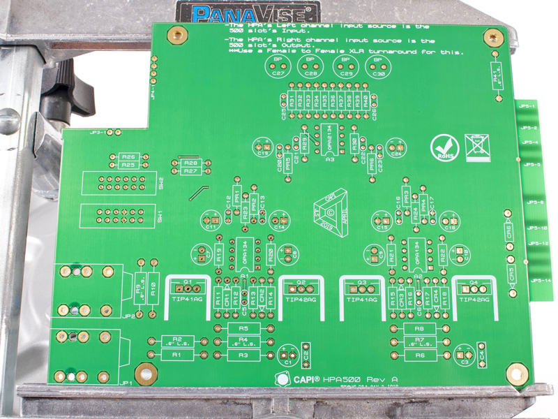
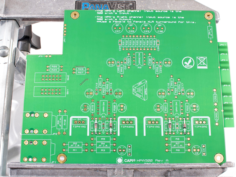
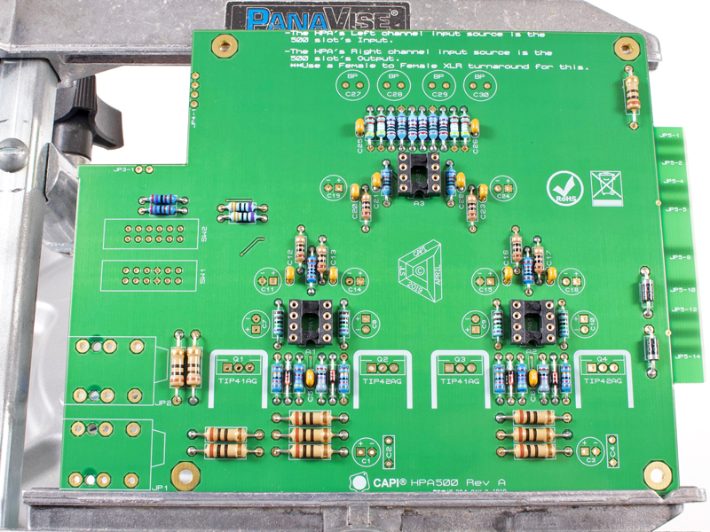
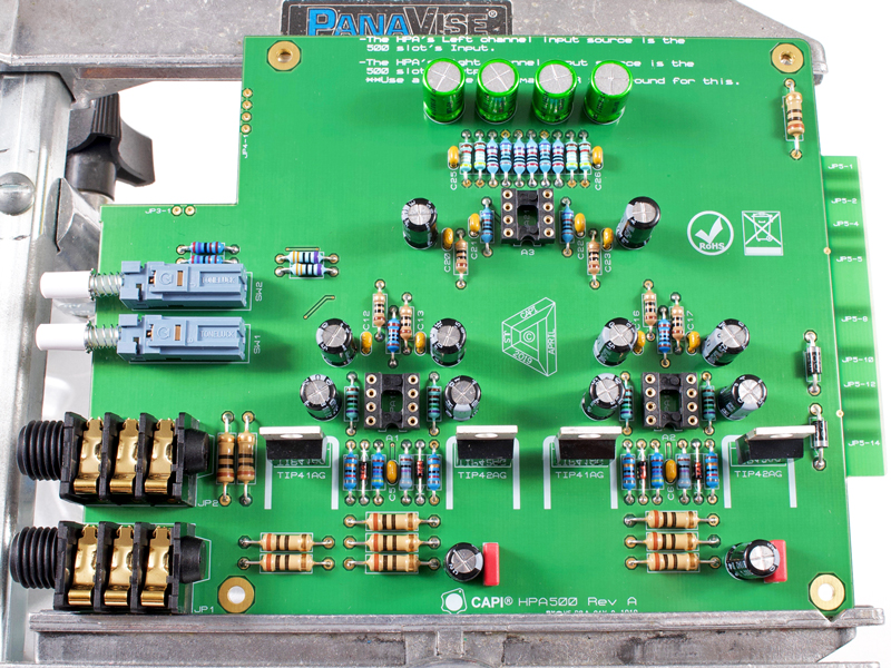
4.0 |
And we begin with a blank canvas.
|
|
Click to enlarge
|
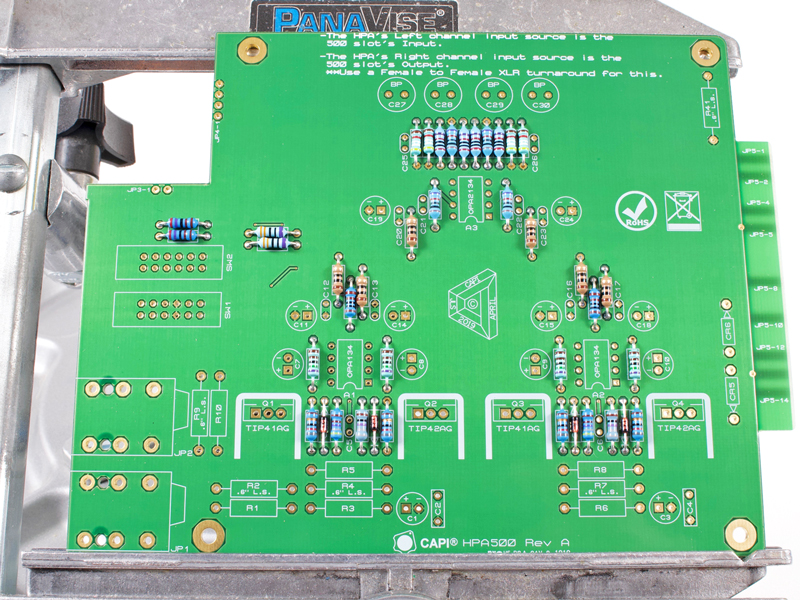
4.1 |
Identify and install the small package diodes.
|
|
Click to enlarge
|
4.2 |
Identify and install all .25W resistors.
|
|
Click to enlarge
|
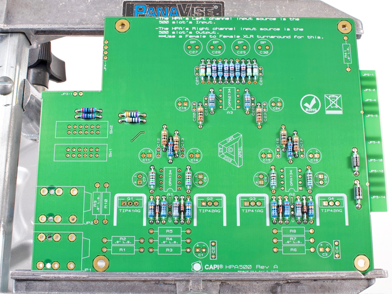
4.3 |
Install the large package diodes.
|
|

Click to enlarge
|
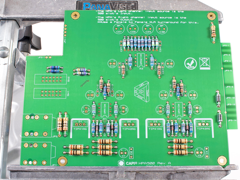
4.4 |
Install the 1W resistors which can be bent on .6" centers and have a 1/2W body size.
|
|
Click to enlarge
|
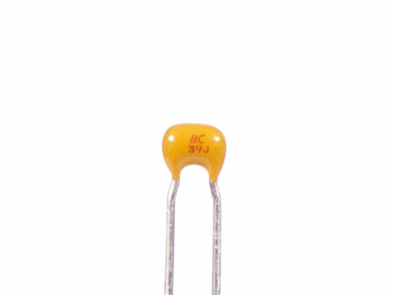
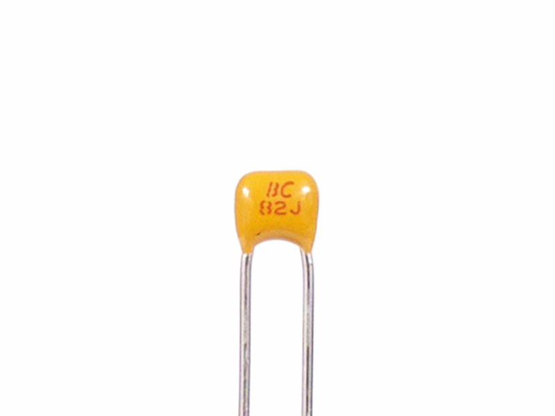
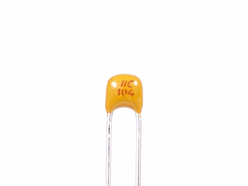
4.5 |
Identify and install the small package ceramic capacitors.
|
|

Click to enlarge
|
4.6 |
Install the IC opamp sockets. Make sure the keyed notch matches that of the silkscreen.
|
|
Click to enlarge
|
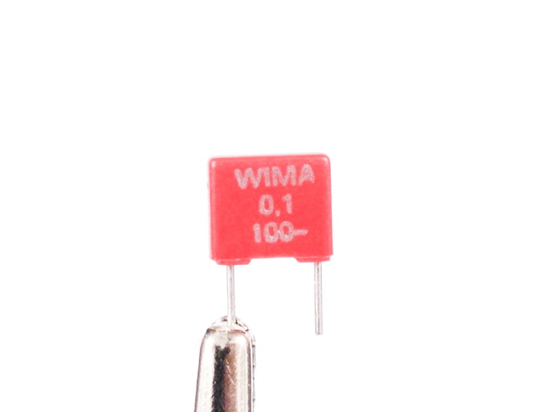
4.7 |
Install the WIMA film caps.
|
|
Click to enlarge
|
4.8 |
Start the install of the two 4PDT mini Toneluck pushbutton switches. Begin by soldering only 2 pins of each switch. Before
soldering all of the pins, check that the switches are fully seated at the rear. Adjust as required. Also check that the
fronts are fully seated. Adjust as required. Solder the remaining switch pins using an alternating order to not overheat
the switch innards.
|
|
Click to enlarge
|
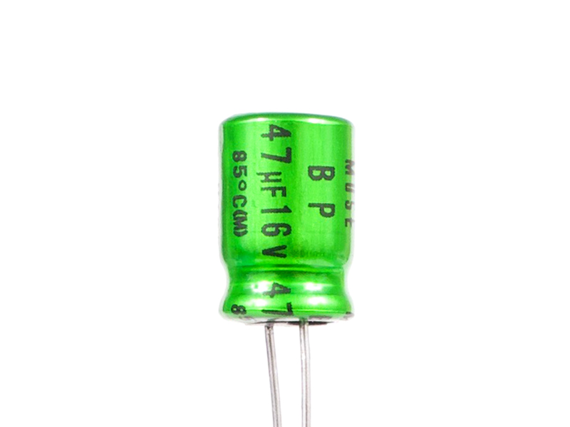
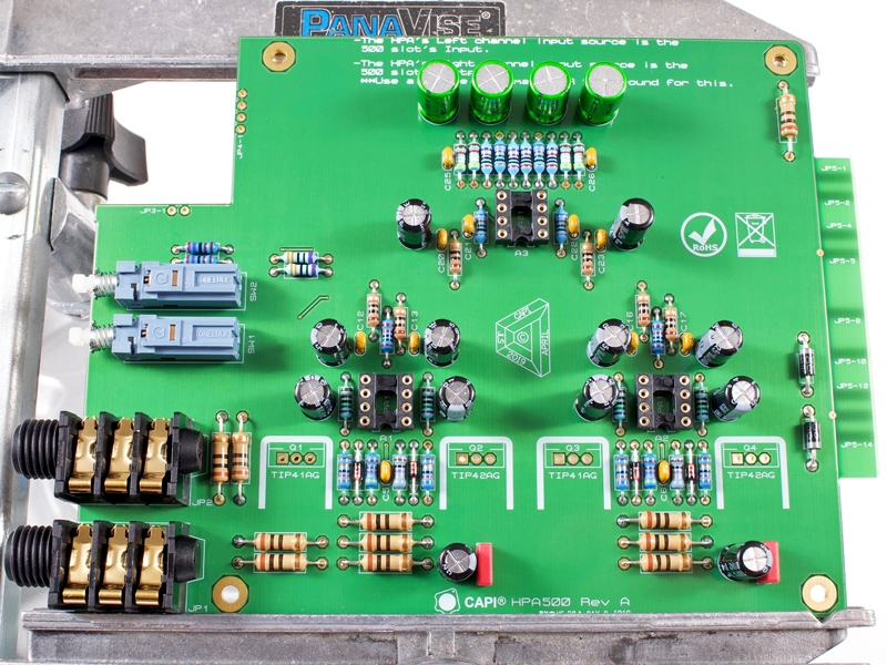
4.9a |
Install the four Nichicon MUSE caps. These are bi-polar electrolytics so direction does not matter.
|
Click to enlarge
|
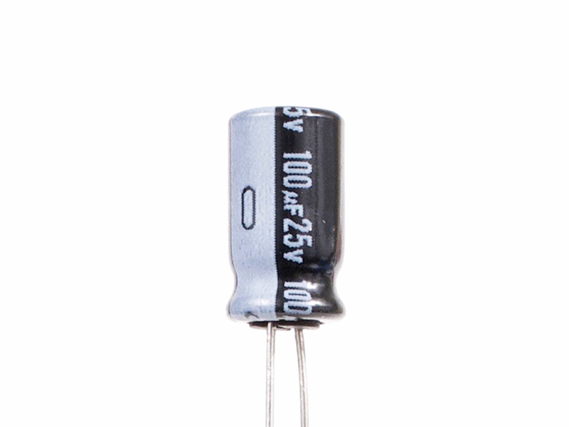
4.9b |
Install the 100µF Nichicon electrolytics. These are polarized so do not put them in the wrong way around!
|
|

Click to enlarge
|
4.10 |
Install the Neutrik jacks making sure they are fully seated and tight to the PCB.
|
|
Click to enlarge
|
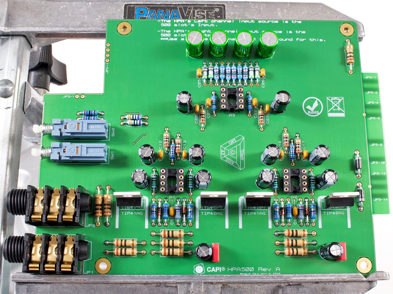
4.11a |
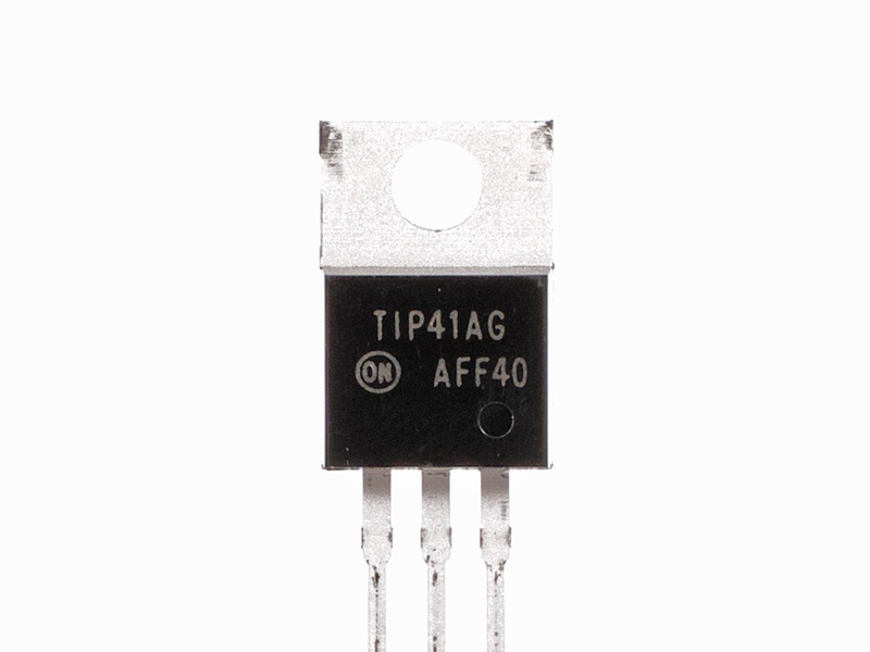
Install the TO-220 output transistors. These absolutely must face the proper direction!
|

Click to enlarge
|
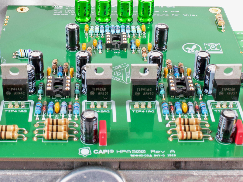
4.11b |
Make sure the output transistor labels match what is printed on the PCB silkscreen at that location. They are not
interchangeable.
|
|
Click to enlarge
|
4.12 |
Install the white pushbutton switch caps on the Toneluck switches.
|
Click to enlarge
|
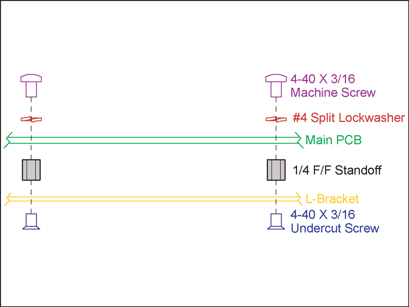
5.1a |
This is the game plan for fixing of the PCB to L-bracket.
|

Click to enlarge
|
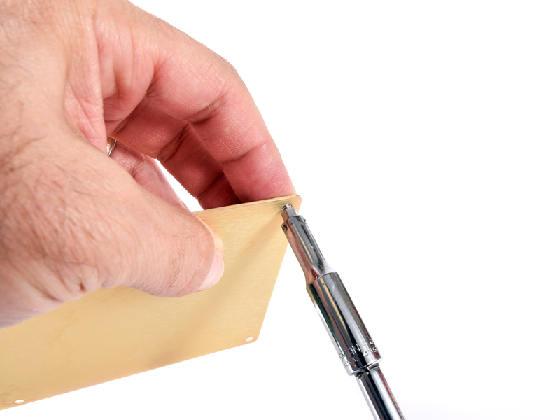
5.1b |
Install the four standoffs to the L-bracket with 3/16" undercut flat head screws. I use a nut driver on the standoffs
which typically works so well that a screwdriver is not needed.
|
|
Click to enlarge
|
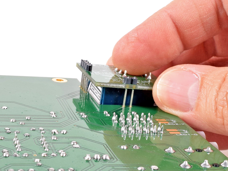
5.2 |
Insert the small Alps-BV PCB into the main PCB from the bottom. DO NOT solder the six header pins at this time.
|
|

|
5.3 |
Flip the PCB assembly over and gently guide it into position in the L-bracket.
|
|
Click to enlarge
|
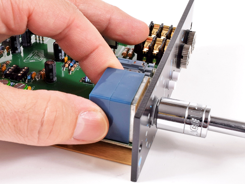
5.4 |
Get all four 3/16" pan head screws and lock washers started into their standoffs but do not fully tighten yet. Make
sure the Alps pot is fully and evenly seated against the L-bracket. Push the PCB assembly towards the back of the
L-bracket and fully tighten all four mounting screws.
|
|
Click to enlarge
|
5.5 |
Lower the faceplate into position.
|
|

Click to enlarge
|
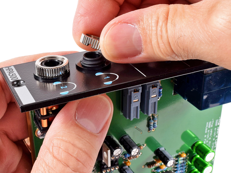
5.6 |
Drop the plastic Neutrik washers over the threaded ends of the jacks. Finger tighten both knurled nuts making sure the
faceplate is parallel to the L-bracket.
|
|
Click to enlarge
|
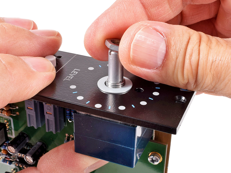
5.7a |
Drop the cupped spring washer over the Alps shaft. Finger tighten the panel nut on the Alps shaft.
|
Click to enlarge
|
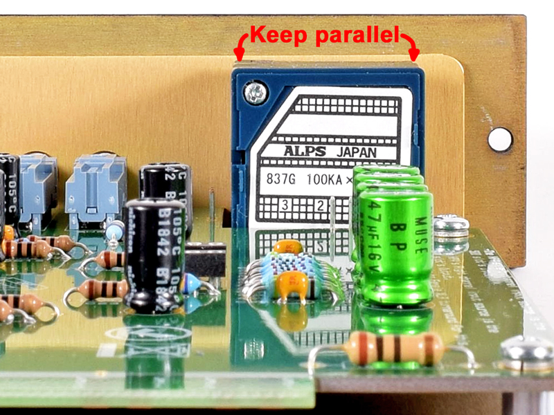
5.7b |
Make sure the top edge of the Alps pot is parallel to the edge of the L-bracket from behind.
|
Click to enlarge
|
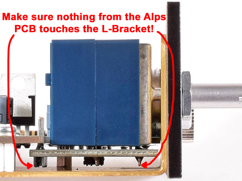
5.7c |
Make sure the Alps PCB subassembly is parallel to the L-bracket from the side. Be sure that no pins or header shrouds are
making contact with the L-bracket.
|

Click to enlarge
|
5.7d |
When you are satisfied with the Alps alignment fully tight the panel nut with an 11mm socket.
|
|
5.7e |
Double check one last time for proper alignment of the Alps pot and the Alps-BV PCB subassembly.
|
Click to enlarge
|
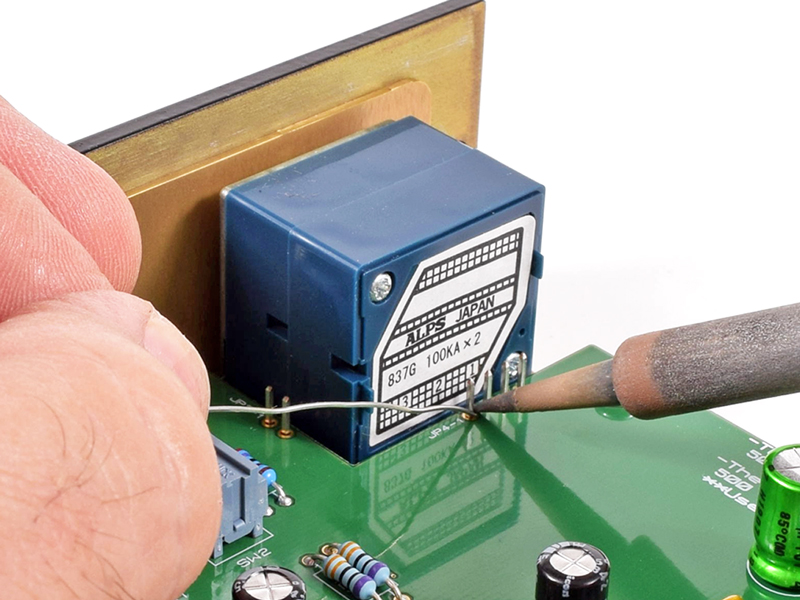
5.7f |
Solder the six header pins from the top side of the main PCB. Trim the pins to be neat and tidy.
**Pro Tip: Hold the waste end of the pin with a needle nose pliers when trimming so you don’t lose them in the
build or put an eye out!
|
|
Click to enlarge
|
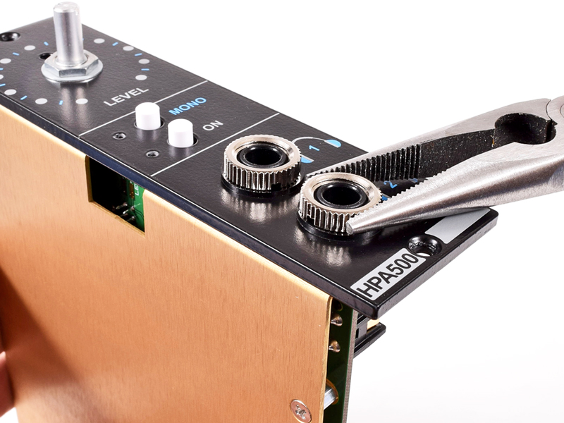
5.8 |
Tighten the Neutrik nuts with a grooved pliers or the like. They don’t have to be gorilla tight just nice and tight.
|
|
Click to enlarge
|
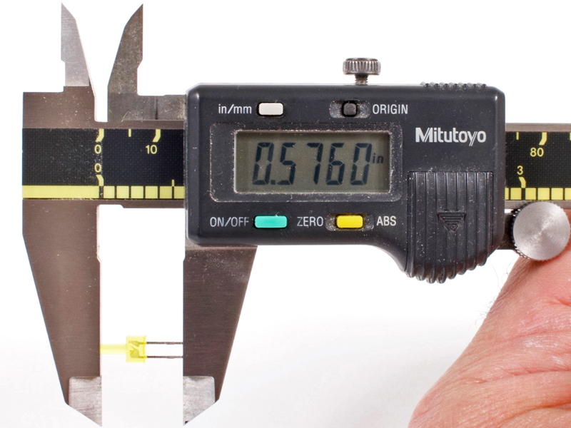
5.9a |
Before trimming the leads, take note as to the difference between cathode and anode on the inside of the LEDs. You will
need to distinguish which is which after cutting the leads. Cut all LEDs to a 9/16" overall length.
|
Click to enlarge
|
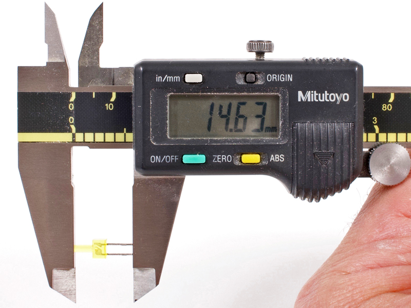
5.9b |
That is appx 14.6mm for anyone not in the USA.
|
Click to enlarge
|
5.9c |
Make some marks on a piece of paper or use something as a jig.
|

Click to enlarge
|
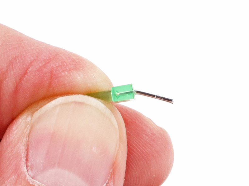
5.9d |
Slightly over-bend the yellow and green LEDs used for pushbutton switch indication.
|
Click to enlarge
|
5.9e |
Lay the the indication LEDs on a flat hard surface and push them downward until flat. This will align the tips of the
leads with the LED body.
|
|
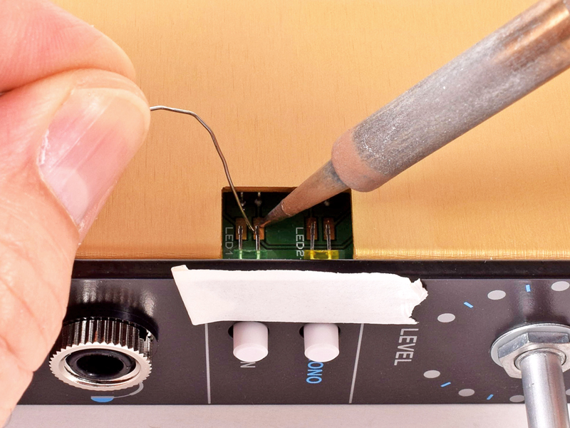
5.9f |
As seen in the next two pics, put a piece of console tape on the faceplate over the LED holes. This will help insure that
your LEDs are flush to the faceplate and also help hold them in place while soldering.
|

Click to enlarge
|
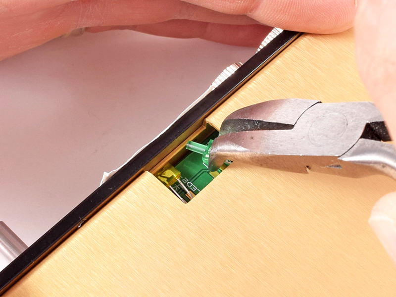
5.9g |
Use a small needle nose pliers or similar to insert the LEDs into their holes.
|

Click to enlarge
|
5.9h |
Push them tight to the console tape. Make sure the leads are touching their respective solder pads and solder them in.
|
|
Click to enlarge
|
5.10a |
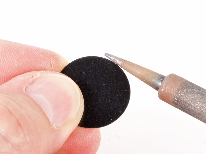
This can be the hardest part of the build. There is a thin protective film over the black insert that should be removed.
If you dig at it with a finger nail, you will likely scratch the top surface of the insert. I have found that slightly
applying heat near the edge of the insert will cause the plastic to melt a little. Be very careful not to torch yourself!
|

Click to enlarge
|
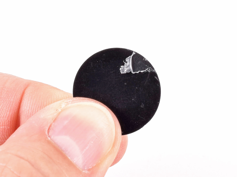
5.10b |
Once you see it starting to shrink back...wait for it to cool and then start to roll it away from the edge with your thumb.
|
Click to enlarge
|
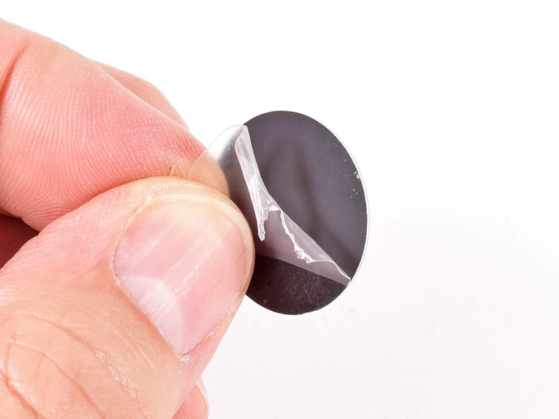
5.10c |
Completely remove the plastic film. Remove the film from the back adhesive side of the insert and install in the most
giant of CAPI® control knobs.
|
|
Click to enlarge
|
5.11 |
Install the knob using a thin piece of cardboard or folded over business card as a spacer. The hex key size is 1/16".
|
|

Click to enlarge
|
5.12a |
Prep the IC opamps for install with the indispensable
IC Pin Straightener.
|
Click to enlarge
|
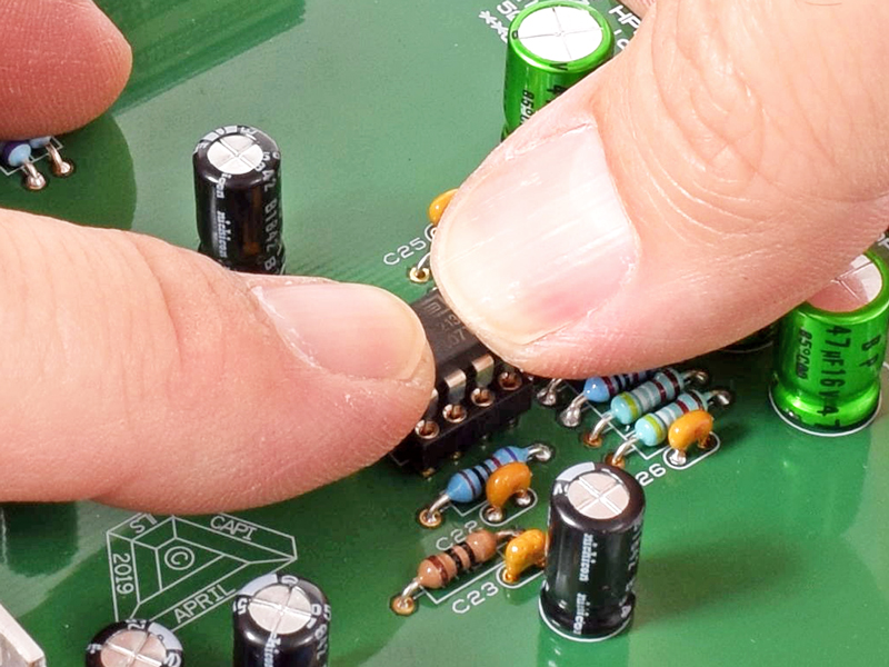
5.12b |
Carefully and gently install the IC opamps into their sockets observing the proper orientation.
|
Click to enlarge
|
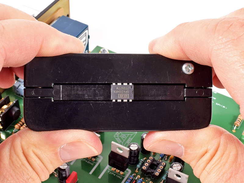
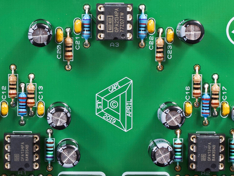
5.12c |
Make sure the parts are correctly placed and rotated the correct way.
|
|
Click to enlarge
|
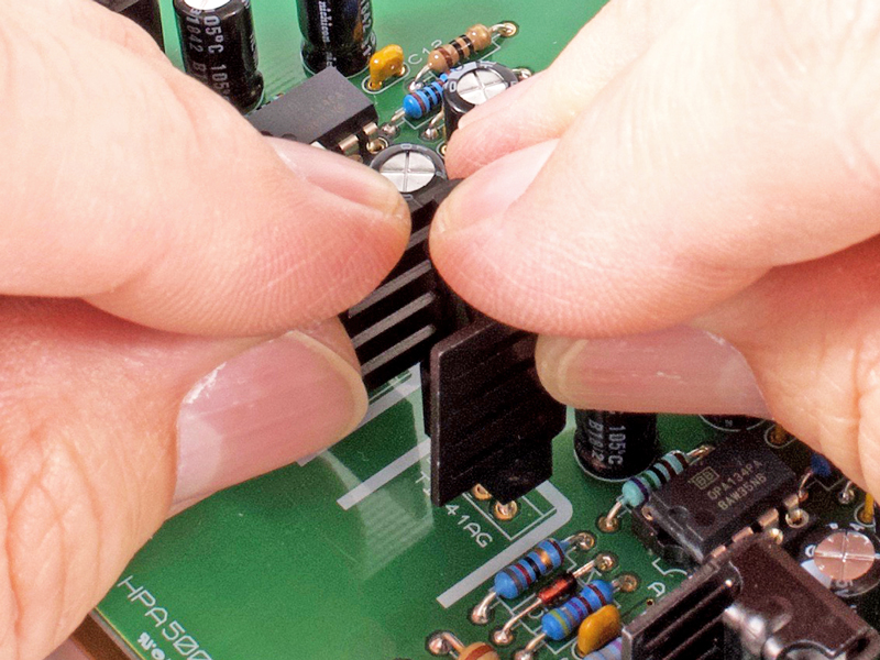
5.13 |
Carefully push the heatsinks onto the four TO-220 output transistors.
|
|
The contents of this assembly guide page, including but not limited to all text, photographs and diagrams, is the
intellectual property of Classic Audio Products, Inc. Reproduction or re-publication by any means whatsoever, whether
electronic, mechanical or electro-mechanical, is strictly prohibited under International Copyright laws. The sole purpose
for this document is to aid in the assembly of the HPA500 Rev A kit offered by Classic Audio Products, Inc.
Commercial use is prohibited.
|
 |
|
Classic Audio Products, Inc. is a DIY parts / kit retailer and provides no direct support for any of the products
available on this site. Support for the kits can be found at the respective [Build] thread at groupdiy.com. Any support
Classic Audio Products, Inc. chooses to provide, is provided "as is" without warranty of any kind. We cannot offer
any guarantee as to the consequences of the support provided. Should the support cause damage or loss of any kind, Classic
Audio Products, Inc. shall not be held liable to you or any other person for indirect, special, punitive, incidental, or
consequential damages or losses. While the successful build rate is extremely high, there is no guaranteed favorable
outcome. Always research and plan any project you undertake thoroughly. Sometimes, a project is over your head, and it
just makes more sense to hire a qualified professional.
|
|
 |
| |
|
|
|
| 0 items |
|
|
|
 |
Curative Notice |
|
|
| Classic Audio Products, Inc. is not affiliated with API.
Customers and fans should not refer to Classic Audio Products, Inc. as "Classic API."
API is a registered trademark of Automated Processes Incorporated. Classic Audio Products, Inc. has no affiliation with
Automated Processes Incorporated. |
|
|
|
|
Bestsellers |
|
|
|
Manufacturers |
|
|
|
Quick Find |
|
|
|
|
|
|
|


 Preface