|
| 511 Rack Pictorial Build Guide |
 |
|
 |
 Preface Preface
The 511 Rack Pictorial Build Guide is written specifically for a DB25 version of the rack kit. If
you are building the all XLR version, simply apply steps from
Section 3 during
Section 4.
That said, this guide is written with the experienced builder in mind. Basic soldering and assembly skills are not
covered here. Neither are basic resistor or capacitor sorting and identifying. Those skills are required and expected
before attempting this build. This is overall an easy build with mechanical assembly skills being just as important as
electronic and soldering skills.
PCB Overlays
 CAPI 511_9-11-VPR-F Rev A Overlay
[Last upload 1/1/2018]
CAPI 511_9-11-VPR-F Rev A Overlay
[Last upload 1/1/2018]
Support Thread
511 Rack [Build] support thread at groupdiy.com
|
Click to enlarge
|
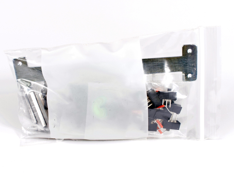
2.0 |
Basic rack carcass fasteners and miscellaneous parts. Everything below that starts with 2.0 is in this bag.
|
 |
Click to enlarge
|
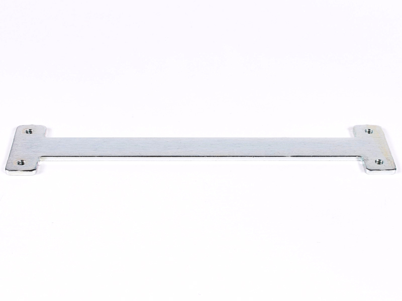
2.0a |
"I" connector for joining the rear metal panels.
|
Click to enlarge
|
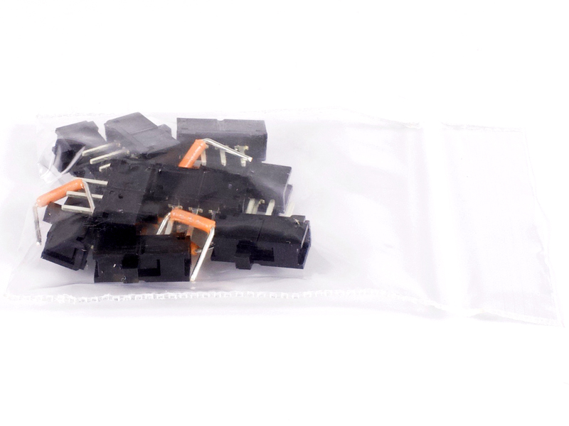
2.0b |
No dot: 6pc orange board to board wire jumpers and 10pc E-Switch slide switches.
|
Click to enlarge
|
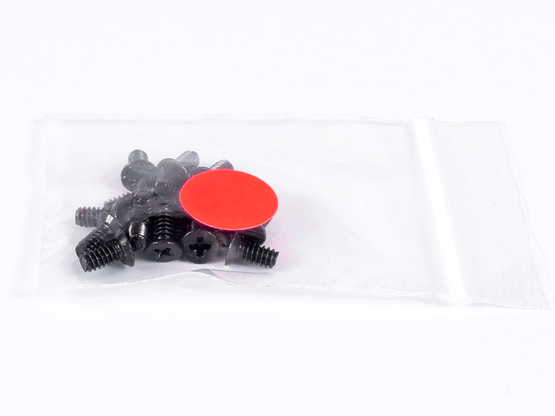
2.0c |
Red dot: 18pc 4-40 X 1/4" undercut flat head screws for securing top/bottom to sides. (2 extra)
|

Click to enlarge
|
2.0d |
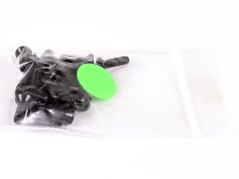
Green dot: 25pc 4-40 X 3/8" oval head screws for securing modules. (3 extra)
|
Click to enlarge
|
2.0e |
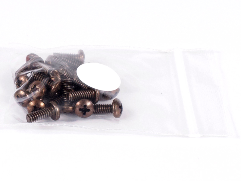
Orange dot: 15pc #4 X 5/16" pan head hi/low thread forming screws for 9-11 and power inlet Neutrik
connectors. (1 extra)
|
Click to enlarge
|
2.0f |
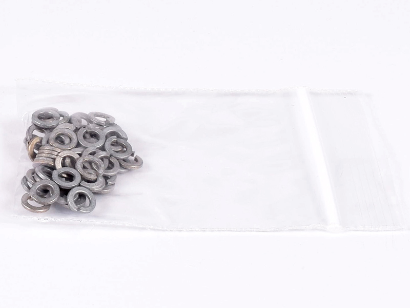
No dot: 58pc #4 split lockwashers. 4pc for "I" connector, 32pc for M3 screws and 18pc for rear panel
perimeter. (4 extra)
|

Click to enlarge
|
2.0g |
White dot: 24pc 4-40 X 5/16" pan head screws. 4pc for "I" connector and 18pc for rear panel perimeter.
(2 extra)
|
Click to enlarge
|
2.0h |
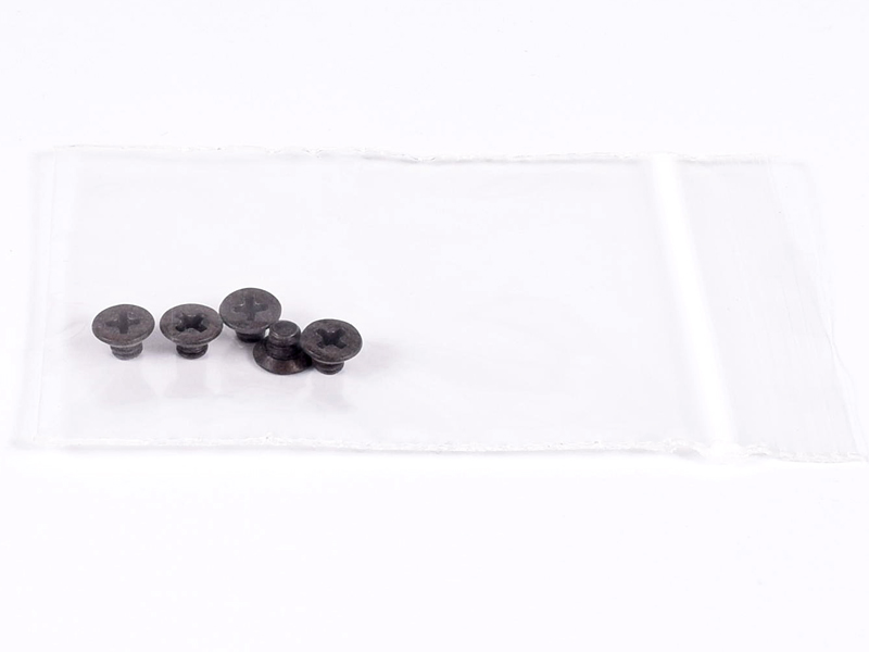
No dot: 5pc 4-40 X 1/8" undercut flat head screws for securing ear plates. (1 extra)
|
Click to enlarge
|
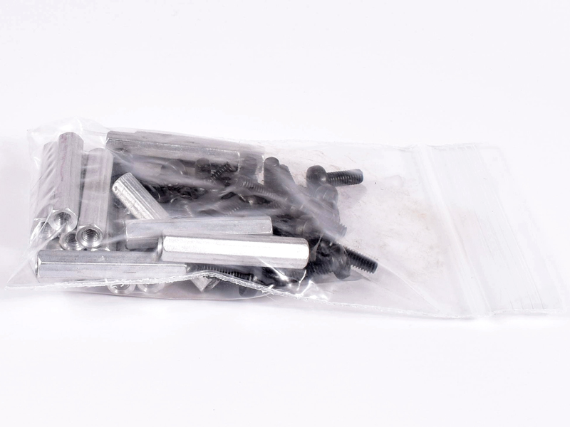
2.0i |
No dot, large bag: 16pc 4.5mm X 24mm standoffs (0 extra) and 33pc M3 X 8mm pan head screws (1 extra).
All are used for securing backplane PCB's to the rear metal panels.
|
|
Click to enlarge
|
2.1 |
Yellow dot: Only included with an all XLR rack kit
33pc #4 X 5/16" pan head hi/low thread forming screws for 1-8 Neutrik connectors. (1 extra)
|
|
Click to enlarge
|
2.2 |
No dot: Only included with a DB25 rack kit
4pc 3/16" AF 4-40 X 3/8" hex steel jack screws and 4pc #4 split lockwashers for securing DB25
connectors to rear metal panel. (0 extra)
|
Click to enlarge
|
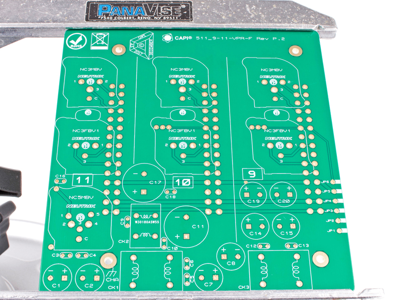
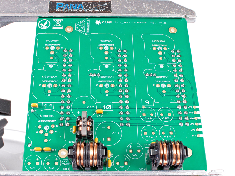
3.0a |
Blank canvas front of 9-11 backplane PCB.
|
|
Click to enlarge
|
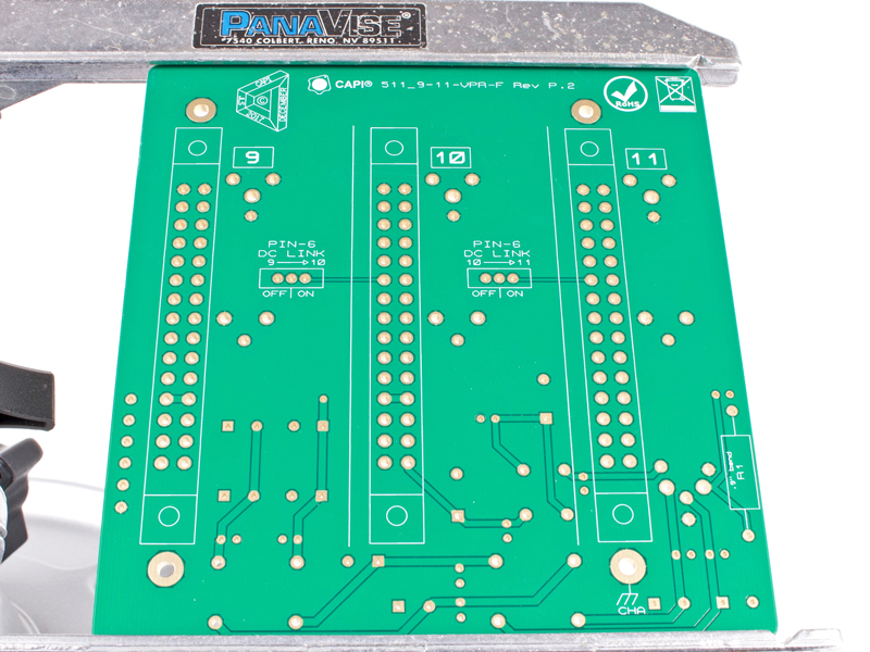
3.0b |
Blank canvas back of 9-11 backplane PCB.
|
|
Click to enlarge
|
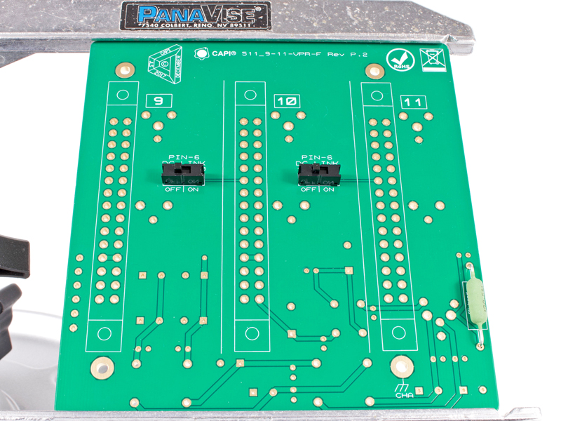
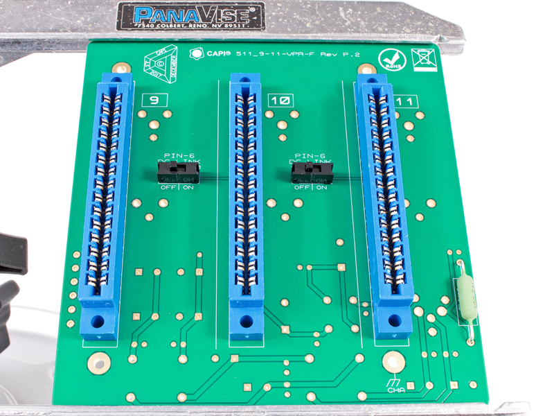
3.1 |
Install the two E-Switch slide switches in the default OFF position.
|
|
Click to enlarge
|
3.2 |
Install the 3W 1 ohm resistor. The holes are 0.9" centers and best if bent on a 1W lead bender jig.
|
|
Click to enlarge
|
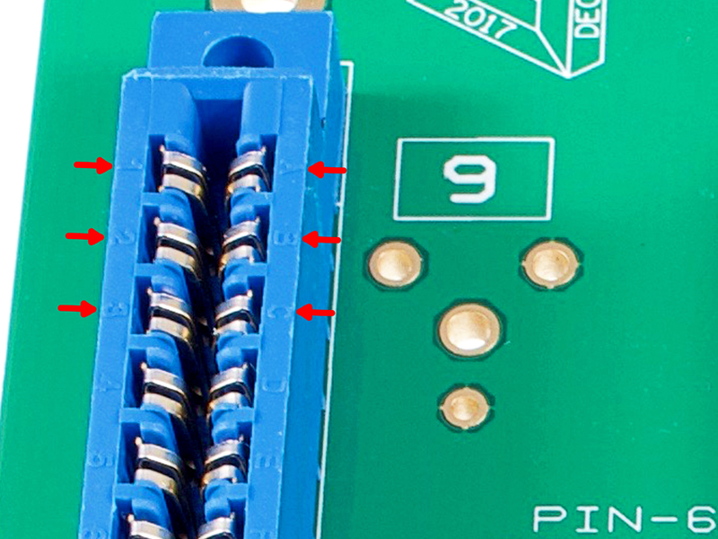
3.3a |
Place and install one of the 30-pin card edge connectors. Note that if you look close, the contacts are label with numbers
on one side and letters on the other. The orientation is not important unless you have to fulfill a slight case of
OCD...like me.
|
|
Click to enlarge
|
3.3b |
Make sure they are flat and tight to the backplane as well as evenly aligned with the silkscreen. Install the other two
connectors.
|
|
Click to enlarge
|
3.4 |
Install the ten .1μF/100V ceramic capacitors. Polarity does not matter.
|
|
Click to enlarge
|
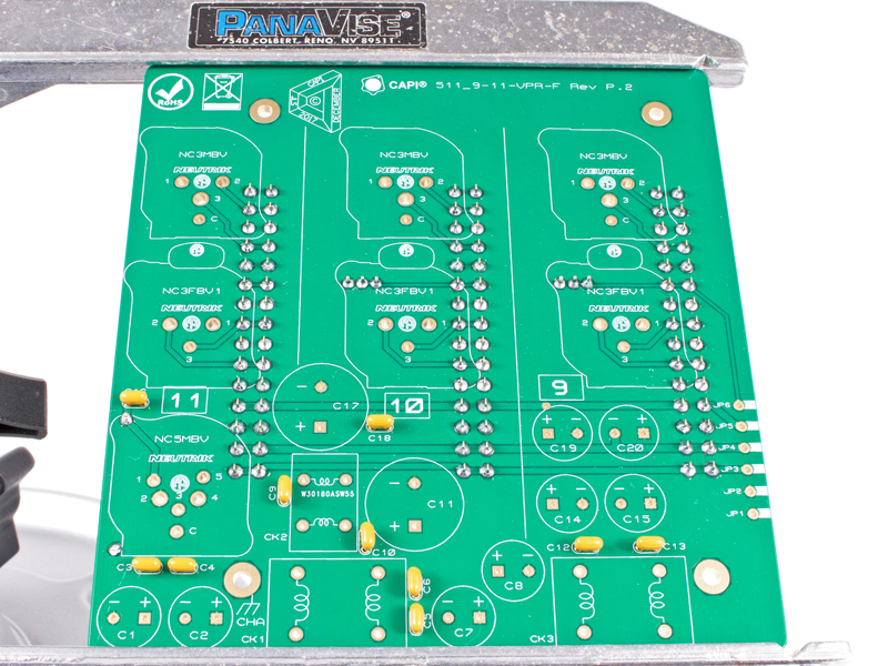
3.5 |
Install the small inductor. Polarity does not matter.
|
|
Click to enlarge
|
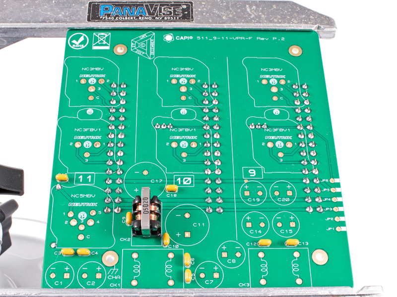
3.6 |
Install the two large inductors. Again, polarity does not matter.
|
|
Click to enlarge
|
3.7 |
Install the two 470μF/63V electrolytic capacitors. Polarity is extremely important here!
|
|
Click to enlarge
|
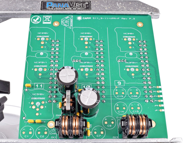
3.8 |
Install the eight 1000μF/25V electrolytic capacitors. Polarity is extremely important here!
|
|
Click to enlarge
|
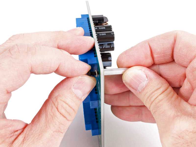
3.9a |
Install four of the M3 screws with lockwashers thru the backplane and into 24mm standoffs.
|
|
Click to enlarge
|
3.9b |
I use a 3/16" nut driver on the standoffs which typically works so well that a screwdriver is not needed.
|
|
Click to enlarge
|
3.10 |
Secure the "I" connector to the 9-11 rear panel using two 5/16" pan head screws and lockwashers.
|
|
Click to enlarge
|
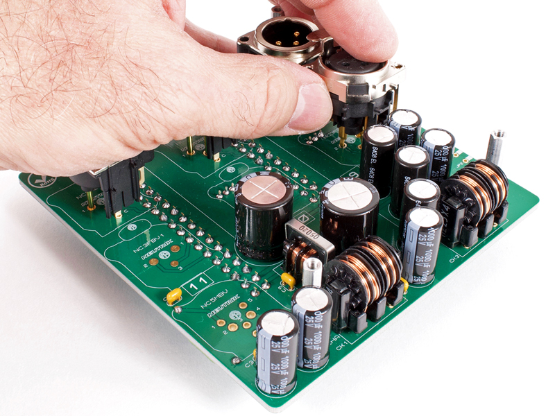
3.11 |
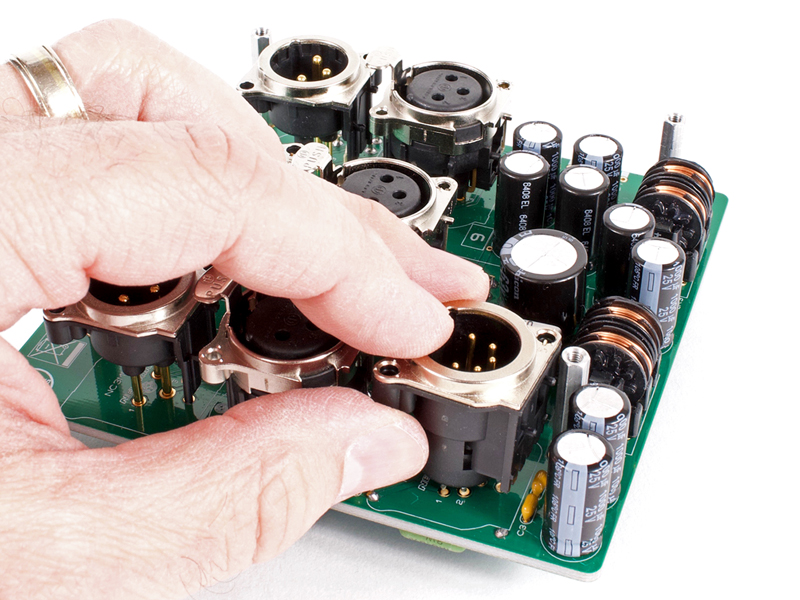
Carefully insert the three 3-pin male Neutrik XLR's fully into their positions. DO NOT solder at this time!
|
|

Click to enlarge
|
3.12 |
Carefully insert the three female Neutrik XLR's fully into their positions. DO NOT solder at this time!
|
|

Click to enlarge
|
3.13 |
Carefully insert the 5-pin Neutrik XLR fully into position. DO NOT solder at this time!
|
|

Click to enlarge
|
3.14a |
Slip the 9-11 rear metal panel into position over the XLR tabs and connector bodies.
|
|
Click to enlarge
|
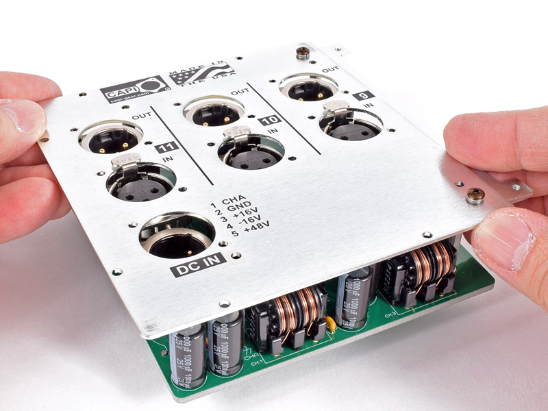
3.14b |
Secure the back panel to the four 24mm standoffs with M3 screws and lockwashers. It is important to start all four screws
before fully tightening any of them.
|
|
Click to enlarge
|
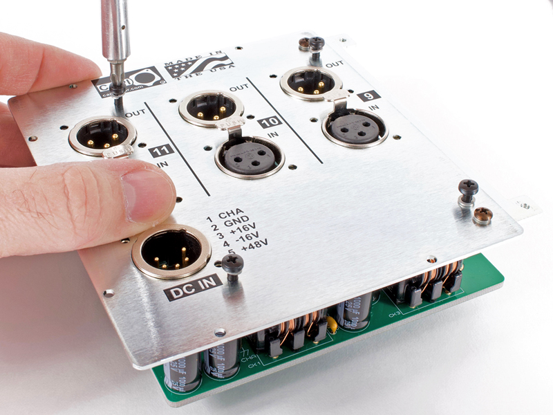
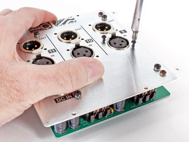
3.14c |
Secure all seven Neutrik XLR connectors with the pan head Hi/Low threaded screws. These screws self-tap into the
connectors but need a moderate amount of downward force. I recommend starting both screws in a respective connector before
fully tightening either of them. DO NOT over tighten or they may strip!
|
|
Click to enlarge
|
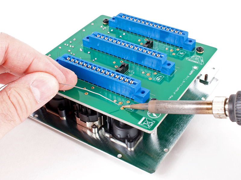
3.15 |
Flip the assembly over and solder all XLR pins. Try not to melt any of the card edge connectors by slapping your soldering
iron into them :-)
|
Click to enlarge
|
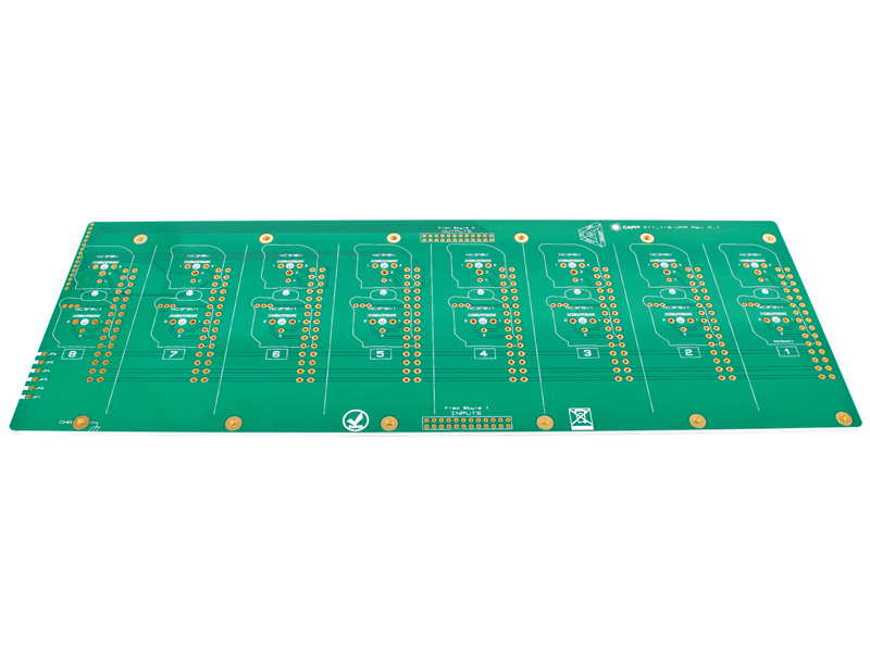
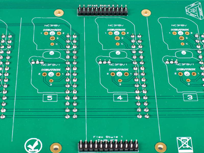
4.0a |
Blank canvas front of 1-8 backplane PCB.
|
|
Click to enlarge
|
4.0b |
Blank canvas back of 1-8 backplane PCB.
|
|

Click to enlarge
|
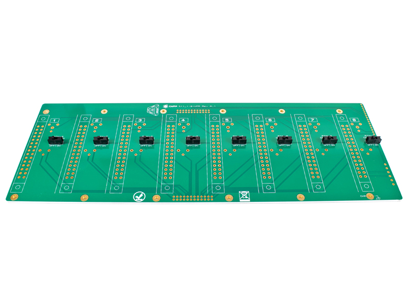
4.1 |
Install the eight E-Switch slide switches in the default OFF position.
|
|
Click to enlarge
|
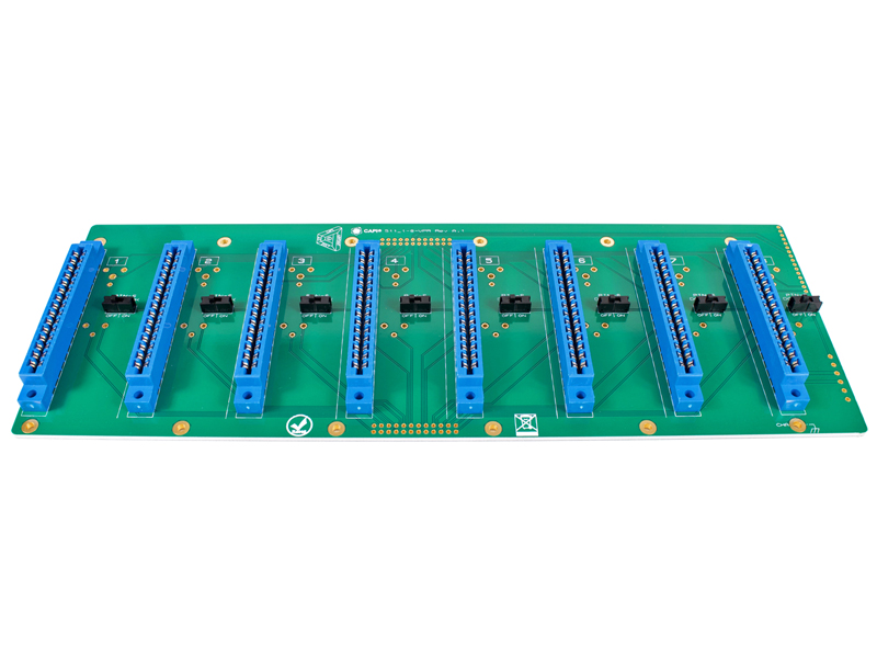
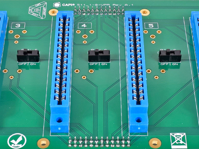
4.2 |
Place and install the eight 30-pin card edge connectors. Make sure they are flat and tight to the backplane as well as
evenly aligned with the silkscreen. Don't forget the OCD note mentioned above in section 3.3a.
|
|

Click to enlarge
|
4.3a |
Install both 24-pin .1" headers from the back of the PCB and then solder from the front side.
|
|
Click to enlarge
|
4.3b |
Check for solder bridges thru a magnifying glass.
|
|
Click to enlarge
|
4.4a |
Install the twelve M3 screws with lockwashers thru the backplane and into 24mm standoffs.
|
|
Click to enlarge
|
4.4b |
Use a 3/16" nut driver on the standoffs which typically works so well that a screwdriver is not needed.
|
|

Click to enlarge
|
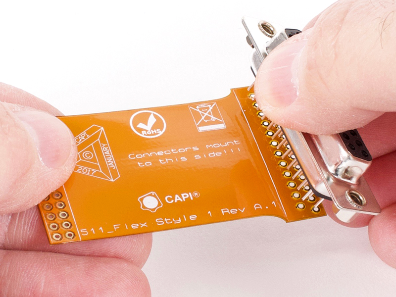
4.5a |
Install a DB25 connector into the Flex Style 1 PCB from the silkscreen side as shown. This IS NOT reversible!
|
|
Click to enlarge
|
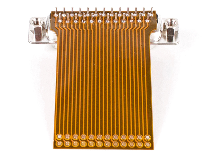
4.5b |
Solder the from the trace side of the flex PCB. Check for solder bridges thru a magnifying glass.
|
|
Click to enlarge
|
4.6a |
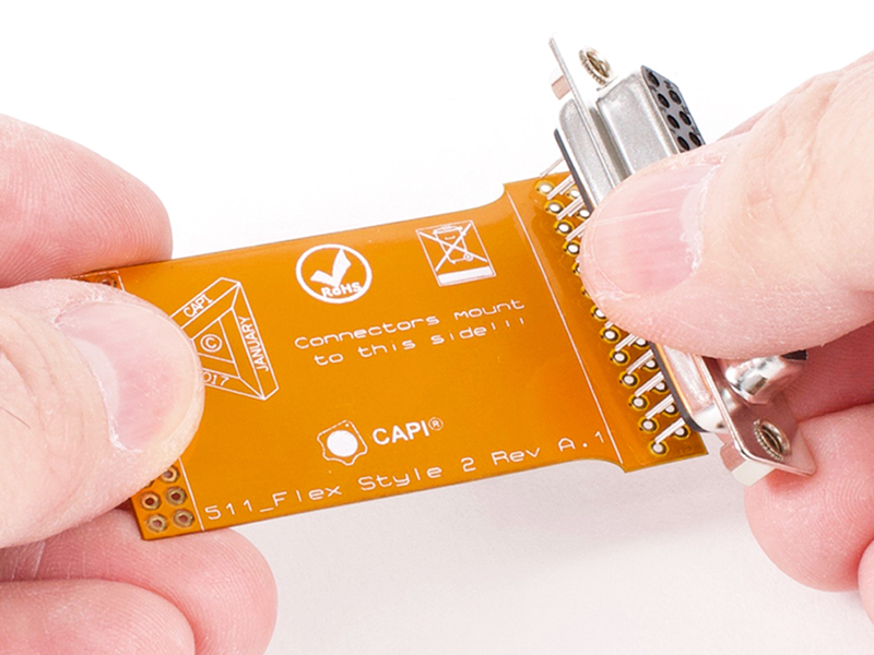
Install the other DB25 connector into the Flex Style 2 PCB from the silkscreen side as shown. This IS NOT
reversible!
|
|
Click to enlarge
|
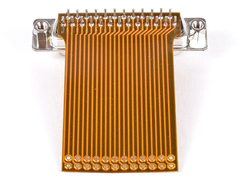
4.6b |
Solder the from the trace side of the flex PCB. Check for solder bridges thru a magnifying glass.
|
|
Click to enlarge
|
4.7a |
Install the Flex Style 1 assembly onto the 24-pin header from the back side of the backplane. This assembly MUST go
to the header labelled "Flex Style 1".
|
|
Click to enlarge
|
4.7b |
Solder the flex PCB in place. Check for solder bridges thru a magnifying glass.
|
|
Click to enlarge
|
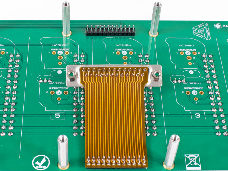
4.8a |
Install the Flex Style 2 assembly onto the 24-pin header from the back side of the backplane. This assembly MUST go
to the header labelled "Flex Style 2".
|
|
Click to enlarge
|
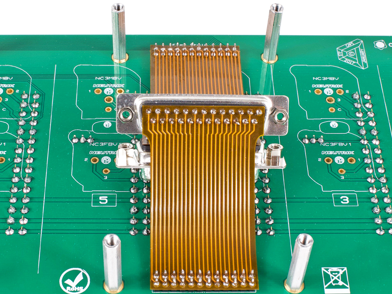
4.8b |
Solder the flex PCB in place. Check for solder bridges thru a magnifying glass.
|
|
Click to enlarge
|
4.9 |
Gently bend a loop in both flex PCB's so the black part of the connector is approximately parallel to the back of the
PCB backplane.
|
|
Click to enlarge
|
4.10 |
Slide the 1-8 rear metal panel into place while guiding the DB25's into their respective holes.
|
|
Click to enlarge
|
4.11 |
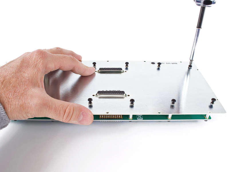
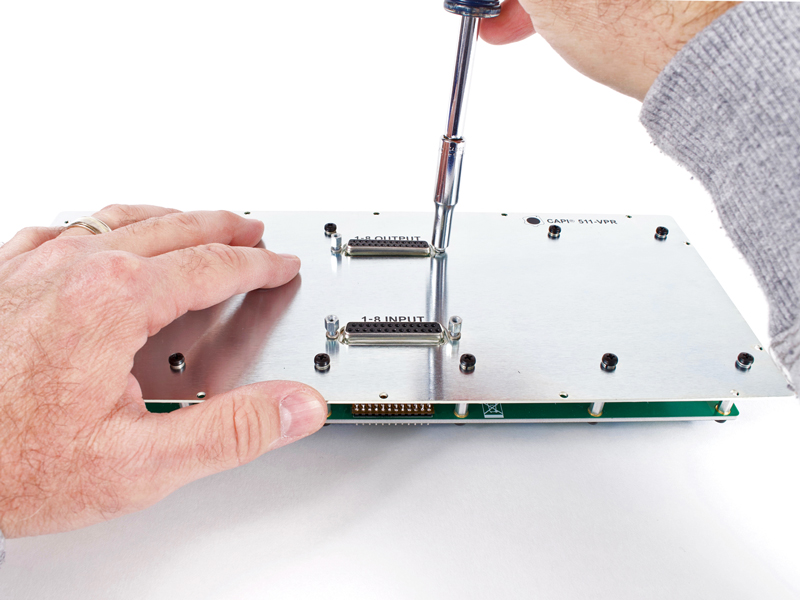
Secure the back panel to the twelve 24mm standoffs with M3 screws and lockwashers. It is important to start all twelve
screws before fully tightening any of them.
|
|

Click to enlarge
|
4.12 |
Secure the DB25 connectors to the rear panel with the jack screws and lockwashers. DO NOT use gorilla force when
tightening or you may sheer one off. If that happens, you may have a mess on your hands :-/
|
|
Click to enlarge
|
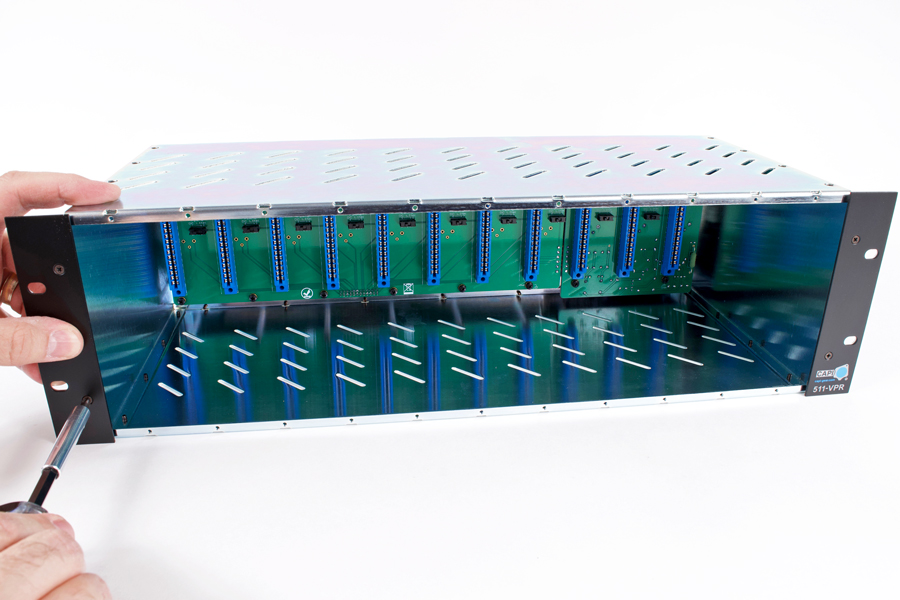
4.13 |
The inside will look something like this.
|
Click to enlarge
|
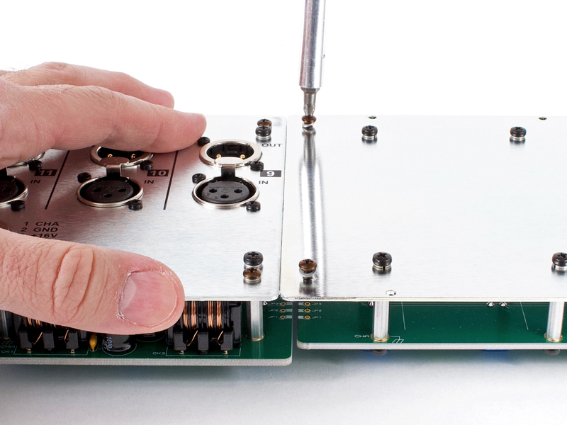
5.1 |
Start both 4-40 X 5/16" pan head screws and lockwashers thru the 1-8 rear metal panel into the "I"
connector and then fully tighten.
|
|
Click to enlarge
|
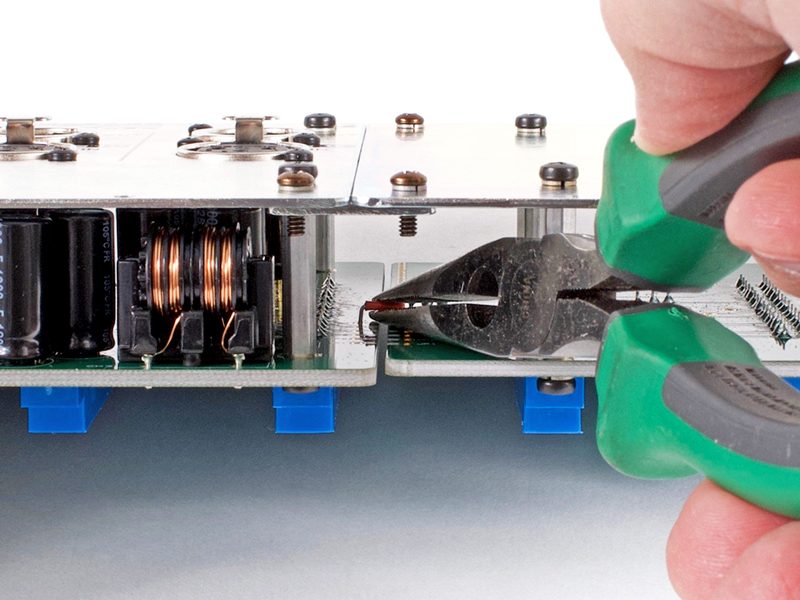
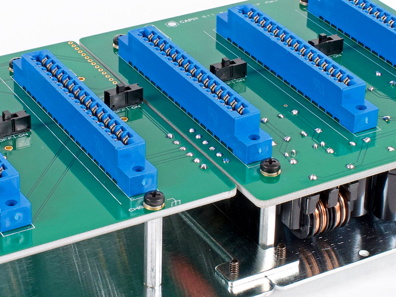
5.2 |
Using needle nose pliers or similar, insert the six orange pre-bent jumpers into their thru holes.
|
|
Click to enlarge
|
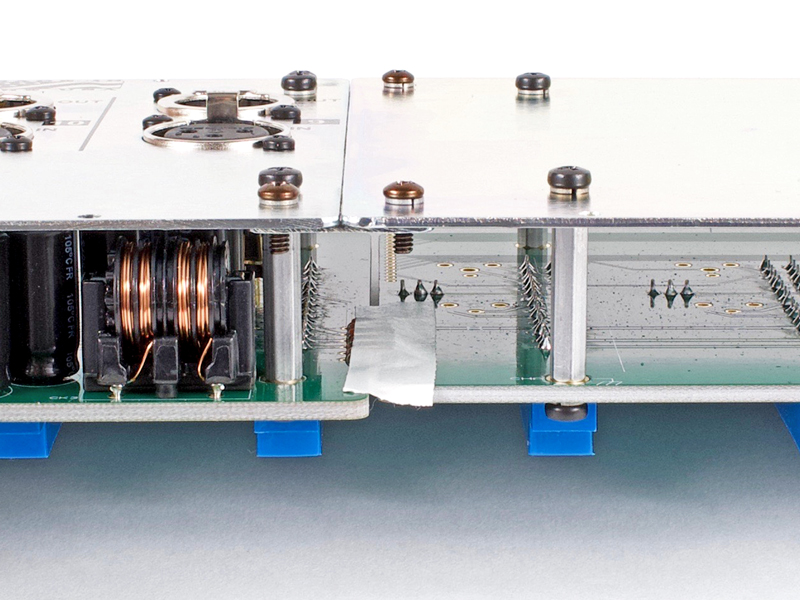
5.3 |
Use a piece of tape from the rear side to hold the jumper wires in place while soldering.
|
|
Click to enlarge
|
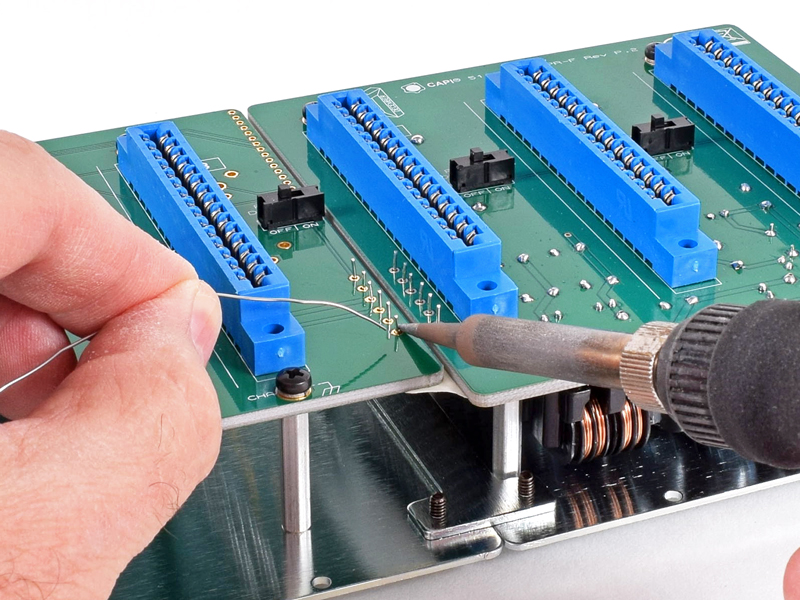
5.4 |
Flip the assembly over and solder the jumper wire leads.
|
|
Click to enlarge
|
5.5 |
As a precaution, trim the jumper wire leads.
|
|
Click to enlarge
|
5.6 |
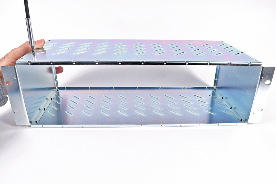
Attach one of the top/bottom panels to one of the sides using four of the 4-40 X 1/4" undercut flat head
screws. Nearly snug them but do not fully tighten at this time. Make sure the orientation of the top/bottom panel is
correct in relation to the side. The edge with eleven threaded holes should be adjacent to the rack ear flange. The edge
with seven threaded holes goes to the back.
|
|
Click to enlarge
|
5.7 |
Attach the 2nd side using four of the 4-40 X 1/4" undercut flat head screws. Nearly snug them but do not fully
tighten at this time.
|
|
Click to enlarge
|
5.8 |
Attach the 2nd top/bottom panel using eight of the 4-40 X 1/4" undercut flat head screws taking note of the
front and back edges. Nearly snug them but do not fully tighten at this time. The entire assembly should have some wiggle
room for adjustment.
|
|
Click to enlarge
|
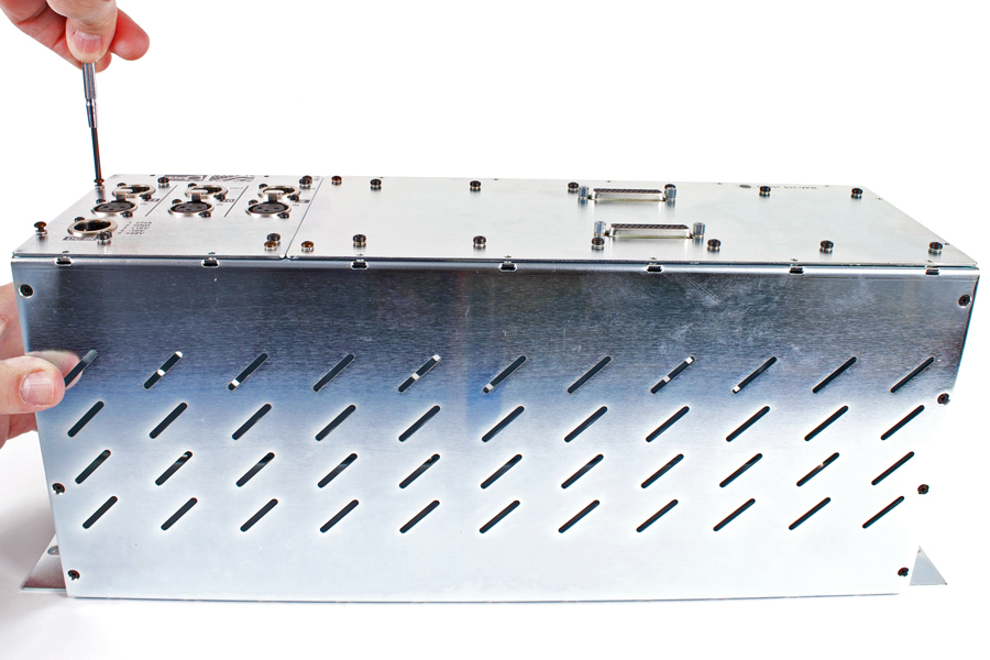
5.9a |
Begin securing the rear panel assembly by starting two of the 4-40 X 5/16" pan head screws and lockwashers
thru into one of the sides. DO NOT fully tighten at this time.
|
|
Click to enlarge
|
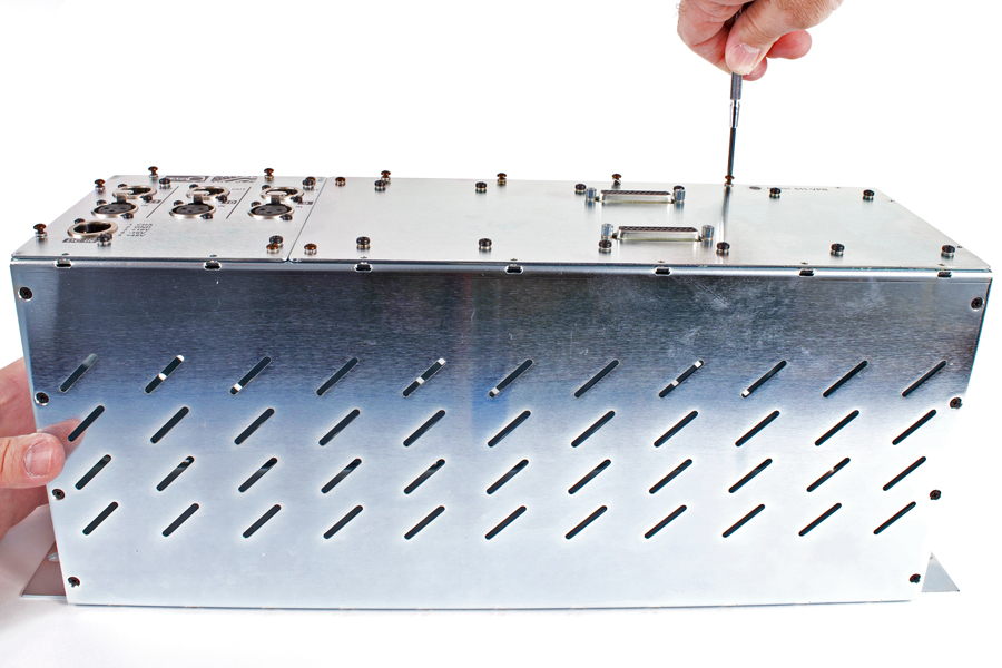
5.9b |
Continue working clockwise around the perimeter by starting 4-40 X 5/16" pan head screws and lockwashers.
DO NOT fully tighten at this time.
|
|
Click to enlarge
|
5.9c |
Once all perimeter 4-40 X 5/16" pan head screws and lockwashers have been started, work clockwise around the
perimeter and fully tighten all eighteen screws.
|
|
Click to enlarge
|
5.10 |
Fully tighten all sixteen 4-40 X 1/4" undercut flat head screws that secure the top/bottom panels to the
sides. DO NOT use gorilla force when tightening or you may sheer one off.
|
|
Click to enlarge
|
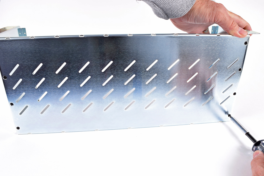
5.11 |
Install both ear plates using 4-40 X 1/8" undercut flat head screws. DO NOT use gorilla force when
tightening or you may strip one of the screws. It doesn't take much to hold them in place.
|
|
The contents of this assembly guide page, including but not limited to all text, photographs and diagrams, is the
intellectual property of Classic Audio Products, Inc. Reproduction or re-publication by any means whatsoever, whether
electronic, mechanical or electro-mechanical, is strictly prohibited under International Copyright laws. The sole purpose
for this document is to aid in the assembly of the 511 Rack kit offered by Classic Audio Products, Inc.
Commercial use is prohibited.
|
 |
|
Classic Audio Products, Inc. is a DIY parts / kit retailer and provides no direct support for any of the products
available on this site. Support for the kits can be found at the respective [Build] thread at groupdiy.com. Any support
Classic Audio Products, Inc. chooses to provide, is provided "as is" without warranty of any kind. We cannot offer
any guarantee as to the consequences of the support provided. Should the support cause damage or loss of any kind, Classic
Audio Products, Inc. shall not be held liable to you or any other person for indirect, special, punitive, incidental, or
consequential damages or losses. While the successful build rate is extremely high, there is no guaranteed favorable
outcome. Always research and plan any project you undertake thoroughly. Sometimes, a project is over your head, and it
just makes more sense to hire a qualified professional.
|
|
 |
| |
|
|
|
| 0 items |
|
|
|
 |
Curative Notice |
|
|
| Classic Audio Products, Inc. is not affiliated with API.
Customers and fans should not refer to Classic Audio Products, Inc. as "Classic API."
API is a registered trademark of Automated Processes Incorporated. Classic Audio Products, Inc. has no affiliation with
Automated Processes Incorporated. |
|
|
|
|
Bestsellers |
|
|
|
Manufacturers |
|
|
|
Quick Find |
|
|
|
|
|
|
|